Executive Summary
GNSS positioning above 70°N fails due to poor satellite geometry (no overhead passes), ionospheric scintillation (98% L2 cycle slip rates during geomagnetic storms), and IMU coast limitations. Recent neural network research shows 38–76% error reduction during outages, but remains experimental. Current industry standards provide no Arctic-specific guidance. We specify the IMU grades, acoustic backup, and space weather monitoring required for DP, survey, and subsea operations in the High Arctic.
The Problem No One Wants to Admit
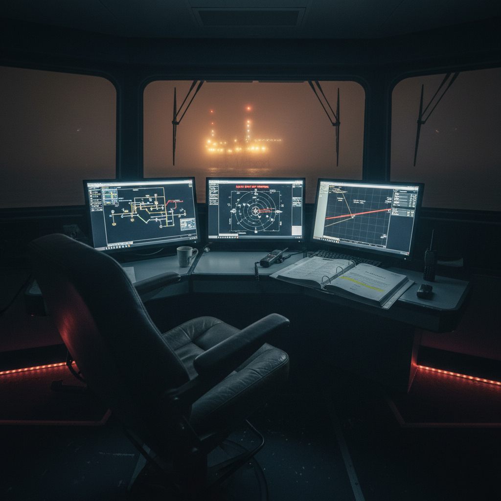
Here’s what we observed in the Barents Sea: Dynamically positioned vessels lose the integrity of their coordinate systems due to geomagnetic anomalies. Seismic surveys that were previously successful fail after 48 hours GNSS outages. Also note the fault reports – when operators discover, mid-operation, that their tactical inertial measurement units (IMUs) in coastal navigation mode are only providing 30 seconds of usable time instead of the expected 5 minutes. Positioning devices from the North Sea are deployed in the Arctic Ocean. Above 70° North? There, these devices simply fail – IMCA S 022 and IOGP 373-19 don’t even mention these failures. These aren’t mere theories, but costly lessons involving delays and risks that most would rather ignore. GPS satellites rotate at an angle of 55°, meaning they are never directly overhead above this latitude. At 70° North, relatively low satellite elevation angles are to be expected. Vertical accuracy suffers. PPP convergence times are extremely slow. With faulty satellite geometry, the number of RTK satellites drops below the minimum. Add to that ionospheric distortions caused by the aurora oval, and what’s the result? Complete and irreversible positional chaos.
What Actually Happens at High Latitudes
Want to see the data? The Technical University of Denmark measured this chaos in Greenland during moderate storms ( Kp 5-6). The RTK ambiguity resolution success rate dropped by 27-37% – time for a solution? It quadrupled – and under strong scintillation, L2 cycle failures reached an incredible 98%. Not a typo. When both L1 and L2 are affected – which would be the case at around 75° north magnetic latitude – dual-frequency receivers fail. The scintillation phase index (σφ) regularly exceeds 0.5 radians under active conditions. The Norwegian Mapping Agency provides examples: CPOS service availability drops below 95% when geomagnetic anomalies are severe in northern Norway. Around Tromsø (69°; 6°N), about 30 positional degradations per year are expected. And what about Svalbard at 78°N? Amazingly, the lights never go out there. Remember the geomagnetic storm on St. Patrick’s Day 2015 ( Kp = 8)? That storm swept across northern Scandinavia, crippling GNSS systems. Shipping operations were halted. And what about the Halloween storm of 2003? Similar fate – research in the Norwegian Sea was paralyzed for up to 48 hours. Each lost day could cost between $500,000 and $1,000,000. The floating production, storage, and loading unit Goliat, anchored at 71°3°N in the Barents Sea, has learned the hard way since 2016 that GNSS and dynamic positioning alerts never stop during prolonged space weather events. Equinor has gone to great lengths to integrate GNSS contingency plans for geomagnetic eruptions into its Arctic drilling campaigns – because it would be foolish not to.
The IMU Can’t Save You
When GNSS fails, many believe they can simply rely on inertial navigation. But beware: The assumption that a modern IMU can compensate for short outages with minimal drift is unrealistic. Sure, in the North Sea, where outages last only seconds, that might be true, but in the Arctic? Scintillation events can distort your position data for minutes or even hours. Position INS depend entirely on IMU quality. FOG or RLG navigation systems drift at 0.8 to 1.5 nautical miles per hour. After just 60 seconds, you can expect an error of about one meter. After 300 seconds, it’s 5 meters, and after 600 seconds, 15 meters. And what about tactical MEMS modules? They drift at 5 to 15 nautical miles per hour. So, after 60 seconds, the error is 5 meters. If the reaction time increases to 300 seconds, the accuracy drops to just 50 meters. If this continues, utter chaos will ensue. For dynamic positioning systems requiring 1–2 meter accuracy, even navigation-grade IMUs offer only 2–5 minutes of “free time.” Tactical? A maximum of 30–60 seconds. Using tactical MEMS sensors above 70°N and suddenly experiencing a 10-minute delay? Your DP system is doomed unless you have an audible backup. The integrity of the positioning system is compromised. Gyrocompasses at high latitudes? That’s simply absurd – they fail because they rely on the Earth’s rotation. As you approach 70°N, the error drops to 5–14°/hour. As you approach 80°N, it can reach 2–61°/hour. An error of 1–3°? Quite common when using mechanical gyrocompasses above 75°N. Ring laser gyrocompasses and FOG? Better, but don’t expect miracles. Furthermore, arctic temperature cycles cause a deviation in the MEMS sensor offset – the temperature difference between the cabin and outside temperature is 40 to 60 °C. We observed this when transitioning from the heated interior to working on deck; IMU offset doubles in this process.
Neural Networks Are Not the Answer (Yet)
In 2025, Shanghai Maritime University introduced the TCN-LSTM neural network as a solution for predicting INS (Inertial Navigation System) positioning errors during GNSS outages. The technology combines Temporal Convolutional Networks (TCNs) for long-term patterns with a Long Short-Term Memory (LSTM) network for short-term events. Its key feature is a modified dynamic adaptive reliable extended Kalman filter (LSTM) that dynamically adjusts the process noise covariance and discards unreliable measurements. In Arctic tests, it reduced errors by 47% for 50-second GNSS outages, 38% for 140-second outages, and 76% for 400-second outages compared to a standard LSTM. A 76% error reduction? But this is where the limit of generalizability lies. The tests were conducted with a single dataset, and if IMU is changed, the entire network has to be retrained. Period. And what about the required computing power? It’s zero. We don’t know if the whole thing even works in real time on embedded systems. The method also ignores the degradation of the reference course signal. There are no validations against navigation-quality IMU reference values. Independent third-party verification? Forget it. In short: This is pure research fantasy at the moment. Perhaps it will be ready for use in five years, but if you’re looking for a miracle solution today: Keep looking; there’s nothing interesting here yet.
What the Standards Do Not Tell You
Look, IMCA S 022 – Guide to GNSS Positioning at Sea – is the authoritative document for offshore GNSS operations. It covers multipath propagation, atmospheric influences, and instrument performance in detail, but completely ignores the problems north of 70°N. Warnings of geomagnetic storms are not mentioned. Signal degradation in polar regions is also not addressed. High-latitude redundancy? Forget it. IOGP 373-19 – Geomatics Guide 19 – is no help either. While it covers positioning and navigation principles in detail, it suggests that ionospheric effects are a universal problem. They aren’t. You won’t find a specific correction strategy for polar regions, nothing on GNSS / INS integration, which varies with latitude, and don’t expect any guidance on monitoring space weather indices for quality assurance. The NORSOK standards? While they focus on Arctic operations, they also consider structural design principles and environmental conditions. Specific GNSS performance requirements for areas like the Barents Sea or Svalbard? None.
Current standards assume mid-latitude conditions work everywhere. They assume RTK base stations and SBAS coverage. But that’s a fallacy. Beyond 72° N, EGNOS coverage becomes an illusion, RTK base stations disappear, and real-time corrections over unreliable cellular and internet connections are hardly possible. Even PPP services? Accuracy drops significantly there. Operators have to find their own solutions for Arctic positioning.
Ice Navigation Does Not Solve the Positioning Problem
The idea that ice detection technology solves positioning problems is an illusion. Take EM-Bird from the Alfred Wegener Institute, for example. This helicopter-towed device measures ice thickness, but only using electromagnetic induction at two frequencies – accuracy is at best ±0.1m. It detects vast ice masses, but how does it help with positioning? Not at all. It cannot detect narrow ice ridges and is completely useless over brittle ice. The Rutter Sigma S6 radar optimizes the X-band for ice detection and is therefore excellent for locating icebergs and ice floes at a range of up to 12 nautical miles. But tiny icebergs at a distance of more than 2–3 nautical miles? Impossible. Detection is highly dependent on sea conditions and ice type, and a skilled operator is essential.
Neither EM-Bird nor Sigma S6 will replace satellite ice charts or electromagnetic thickness measurements anytime soon. Neither comes close to achieving the centimeter-level positioning accuracy required for dynamic positioning, pipeline laying, or underwater construction projects. ## What You Actually Need
We traveled north of the 70th parallel. We verified positional data obtained from drilling in the Barents Sea, research in Svalbard, and even seismic surveys in the Arctic. Let’s take a closer look:
1. Deploy Navigation-Grade FOG IMU
Tactical MEMS devices are insufficient. You need a FOG navigation IMU with a drift stability of at least 0.01°/hour, such as the Honeywell HG9900 or the iXblue PHINS – nothing less. This is impossible in dynamic positioning environments, such as surveying. A high-quality tactical fiber-optic gyroscope is suitable, but only if its stability is verified in glide mode before starting the flight. Measure the drift after 60, 120, and 300 seconds with GNSS disabled. Measure it yourself – don’t rely on the manufacturer’s specifications. MEMS devices fail under extreme arctic conditions. If you require a positional accuracy of 2 meters and your IMU drifts 5 meters within 60 seconds, you only have 60 seconds of glide time left, not five minutes. That’s the unfortunate reality.
2. Multi-Constellation Multi-Frequency GNSS
You need at least a four-satellite positioning system: GPS, GLONASS, Galileo, and BeiDou. Frequency multiplication (L1/L2/L5) is essential. Ensure your receiver’s firmware supports the polar ionosphere. Some devices have Arctic-adapted firmware for improved scintillation positioning – use this. GPS only? Satellite images north of 70° North are unusable. GLONASS provides slightly better results at 65° North, but is still weak. Use Galileo and BeiDou as backups. Satellites fail during geomagnetic storms; therefore, have alternative positioning options available.
3. Pre-Deploy LBL Acoustic Array
USBL as a primary backup north of 70°N? You can’t be serious! Before you begin, install a long baseline acoustic (LBL) system. At least four transponders spaced 300 meters apart. Use GNSS for alignment, if available. Once installed, your LBL will provide reliable position data with an accuracy of 10–30 mm (depending on the system configuration). In case of GNSS failure, for example due to geomagnetic storms, switch to LBL. As soon as GNSS is available again, switch back. Leave the system in place at all times. Yes, it’s expensive – mobilizing, installing, and retrieving a four-transponder system costs £50K–£100K. Losing a single day of dynamic positioning is even more costly.
4. Integrate Space Weather Monitoring
Subscribe to alerts from the NOAA Space Weather Prediction Center or the ESA Space Situational Alert System. Monitor the Kp index and ROTI in real time. Consider this in your daily positional risk assessment. Kp index reaches 5? Create contingency plans with backup GNSS. Kp index 6? High positional risk. Kp index 7? Expect prolonged GNSS outages. Plan your operations based on these forecasts. Do not launch critical DP missions if a strong geomagnetic anomaly is predicted within the next 12–24 hours. This is not far-fetched theory. The Kp index at high latitudes and GNSS outages are closely correlated. All the data is available. Use it.
5. Configure Automated Failover
Your DP and navigation systems should automatically switch from GNSS to acoustic positioning/ INS in the event of GNSS failure. Set the following thresholds: GDOP > 4, satellites < 8, cycle loss rate > 5%, differential correction time > 30 seconds. Test the switchover monthly. Simulate GNSS failure and verify that the DP system switches to acoustic or INS mode without your intervention. Ensure that the acoustic system updates the position at a minimum of 1 Hz. The position correction time must not exceed 2 seconds. Manual switching will prove costly if your DPO processes a storm warning at 3:00 AM in January. Automate this process now.
6. Dual Heading Reference
A single GNSS course source is insufficient – use a dual-antenna GNSS course source in combination with an FOG gyrocompass. Continuously compare the readings. At 75° north latitude, gyrocompasses fluctuate; GNSS readings are affected by multipath propagation and low-altitude errors. For added reliability, use two sources. If an FOG gyrocompass is not on board, install one. The cost is between £30K and £80K. Course losses during dynamic positioning operations are significantly more expensive – consider filing a fault report and station loss report.
The Metrics That Matter
Track these metrics. Document them. Test them relentlessly:
-
Position availability: 99.5% for DP, 99.0% for survey. Log outages lasting longer than 10 seconds. Notice a gap? Analyse the cause. If you cannot achieve these metrics, you are not ready for the Arctic.
-
Average GDOP: Calculate the daily average and the 95th percentile. If you find averages above 3.5 or a 95th percentile above 5.0, your satellite geometry is deficient.
-
Drift cycles: Check daily. More than 10 drift cycles per hour? Then you have problems with ionospheric conditions. Monitor these continuously.
-
INS coast performance: Test every month. Disable GNSS for 60, 120, and 300 seconds to determine drift. Compare this drift to specifications. If the deviation exceeds 20%, there is an IMU problem.
-
Acoustic system latency: Monitor the update rate and position lifetime. Is the latency greater than 2 seconds? Check the transponder status or the accuracy of the sound velocity profile.
-
Kp index correlation: Capture this along with position availability. After 6–12 months you will have a correlation database unique to your operations. Use it to adjust your risk assessment. ## What Standards Should Require
Standards organisations like IMCA and IOGP have not published positioning guidance specifically for polar regions. What they should require:
-
Space weather monitoring – mandatory north of 65°N. Kp index, ROTI charts, solar wind speed. Contingency plans for Kp ≥ 6.
-
Minimum IMU class for DP and survey operations north of 70°N. Navigation FOG (0.01°/hr bias stability) for DP2/DP3 vessels. High-quality tactical FOG (minimum 1°/hr) for survey vessels.
-
Acoustic positioning – mandatory for safety-critical operations north of 70°N. LBL preferred, USBL with proven redundancy acceptable.
-
GNSS/INS coast performance testing before entering the Arctic. Define drift tolerances at 60, 120, and 300 seconds for all operation types.
-
Multi-constellation multi-frequency GNSS above 70°N. Minimum GPS + GLONASS + Galileo. Dual-frequency (L1/L2) standard, triple-frequency (L1/L2/L5) recommended.
These requirements do not exist in current standards. Operators must develop their own Arctic positioning procedures until they do.