Executive Summary
Floating-wind site survey scope is set by the mooring and anchor concept, not by the hull, and that concept depends on water depth, metocean regime and soil conditions. Scoping a campaign to a single preferred concept often leads to remobilisation when the concept moves. We present a decision matrix linking depth band and metocean regime to credible mooring and anchor families and their survey consequences. We then set out specific scoping rules for geophysical coverage, geotechnical phasing and metocean measurement.
On this page13 sections
- The scoping decision behind a floating-wind site survey
- Why the concept choice sets survey cost and risk
- Depth, metocean and soil: what governs the choice
- Water depth
- Metocean regime
- Soil conditions
- Five scoping errors that force a second mobilisation
- 1. Scoping the geotechnics to the hull rather than the anchor
- 2. Sizing geophysical coverage to the preferred layout
- 3. Treating the metocean campaign as a wind resource campaign
- 4. Neglecting water-level variation for tension-moored concepts
- 5. Applying fixed-bottom survey specifications at floating-wind depths
- Building the scope from the concept envelope
The scoping decision behind a floating-wind site survey
Every floating-wind site survey is commissioned before the substructure, mooring and anchor concept is fixed, yet that concept decides where the seabed has to be investigated and to what depth. This article sets out our engineering framework for a decision that recurs on floating-wind developments: how far concept selection should constrain the scope of the site survey, and in what order the two should be fixed. A recent paper in Ocean Engineering prompted it; the framework and the judgements in it are our own.
The problem is circular: developers want a survey scope early so that vessel time can be secured and a ground model can feed concept selection. The concept itself depends partly on what that survey finds. Our position is that the circularity can be managed. The method is to scope the survey to the envelope of credible concepts, not to the concept the developer currently prefers, and to phase the geotechnical work so that expensive per-location investigation follows a concept freeze.
Why the concept choice sets survey cost and risk
On a fixed-bottom project, the foundation footprint is close to the turbine position, and the geotechnical scope is broadly one investigation location per foundation plus cable route work. Floating wind does not follow this pattern. The seabed interaction happens at anchors that can be several hundred metres or more from the turbine position, and in some layouts anchors are shared between adjacent units. The survey therefore has to characterise:
- the anchor locations themselves
- the mooring line touchdown and laydown zones
- the dynamic cable touchdown zones
- the static inter-array and export routes
The anchor positions and the soil depth that matters at each of them both depend on the mooring concept.
Getting this wrong costs money in a predictable way. If the geophysical coverage is too narrow for the final anchor radius, or the geotechnical investigation is too shallow for the final anchor type, the result is a second campaign. That campaign usually falls on the critical path between concept selection and FEED, and it is often sequenced into a less favourable weather window than the first. In our view, most of the cost lies in remobilisation, weather risk and schedule slip, not in the extra survey line-kilometres. Extra coverage acquired on the first mobilisation is cheap by comparison.
Depth, metocean and soil: what governs the choice
Three groups of parameters drive concept selection, and each one has a distinct survey consequence.
Water depth
Depth constrains the hull and the mooring geometry. Spar buoys need water depth well in excess of their deep draught, so they suit deeper sites. Semi-submersibles and barges have shallow draughts and work across a wider depth range. Tension-leg platforms are technically feasible across intermediate and deep water, but tendon behaviour makes them sensitive to water-level variation.
Depth matters more for the mooring than for the hull. At the shallow end of floating wind, a pure chain catenary has little geometric compliance. Restoring stiffness and line tension become hard to control, and snap loading becomes a design concern. This pushes designers toward heavier clump-weighted systems, hybrid chain-synthetic lines or in-line compliance elements. In deeper water, catenary footprints become very large, and taut or semi-taut synthetic systems become attractive because they reduce the spread radius and seabed contact. They also change the anchor loading from near-horizontal to inclined or near-vertical.
Metocean regime
The mooring designer needs more than an extreme significant wave height:
- Wave spectral shape and swell content. Peak periods that approach hull natural periods in heave, pitch or roll govern the motion response. Swell-dominated sites behave differently from wind-sea sites with similar Hs.
- Low-frequency forcing. Second-order slow-drift excursions in surge and sway often govern mooring line design, and they depend on the wave group statistics and the full spectral description.
- Current profile through the water column. Current drag on mooring lines and dynamic cables depends on the profile, not on the surface value. Sites exposed to strong tidal flow, density-driven currents or internal waves need full-depth profiling.
- Water-level range. Tidal range plus surge directly sets the pretension margin for TLP tendons and the clearance of taut systems. A TLP becomes much harder to justify at large-tide sites.
- Wind-wave misalignment and directional spreading. Misalignment between wind and waves changes the load cases in DNV-ST-0437 and IEC TS 61400-3-2, and it affects line-by-line tension distribution.
Soil conditions
Soil decides which anchor families are feasible, and anchor type sets the depth and type of investigation:
- Drag embedment anchors suit soft clays and some sands. They need a characterised drag path, not only the final position, and penetration in soft clay can be deep.
- Suction caissons need installable soil, adequate undrained or drained strength profiles, and an absence of boulders or cemented layers across the caisson footprint.
- Driven or drilled piles tolerate a wider range of soils but bring driveability and layered-profile questions.
- Plate anchors suit taut systems in clay. They carry their own installation and keying-loss uncertainties, covered in DNV-RP-E302.
The matrix below brings these together. The depth bands are indicative, and the boundaries between them are soft. Hull motion characteristics, turbine size and local soil can move a site across a boundary.
| Depth band (indicative) | Metocean character | Credible mooring families | Credible anchor families | Primary survey consequence |
|---|---|---|---|---|
| Shallow end of floating (shallower than roughly 60–80 m) | Often tidally dominated, large water-level range possible | Hybrid chain-synthetic, clump-weighted catenary, compliant elements; TLP generally disfavoured where tide plus surge is large | Drag anchors, suction caissons, piles | Large footprint relative to depth; touchdown zones in mobile sediments; shallow-soil strength and bedform mobility dominate |
| Intermediate (roughly 80–200 m) | Mixed wind-sea and swell; tidal and density-driven currents | Catenary and semi-taut both credible; TLP credible at low tidal range | All families credible | Widest concept envelope, so the widest survey envelope; geophysics must cover catenary radius until concept freeze |
| Deep (beyond roughly 200 m) | Swell exposure, deep current structure, internal waves at some sites | Taut and semi-taut synthetic dominate | Suction caissons, piles, plate anchors; vertical load capacity governs | Inclined and vertical uplift loading; deeper geotechnical penetration; deep-tow or autonomous underwater vehicle (AUV) geophysics needed for resolution |
The intermediate band carries the largest scoping risk. Every concept remains credible there, so the survey has to support all of them until the design narrows.
Five scoping errors that force a second mobilisation
1. Scoping the geotechnics to the hull rather than the anchor
Survey specifications sometimes take their structure from the substructure decision, for example “semi-submersible concept, therefore investigation scope X”. The hull type tells you very little about seabed requirements. A semi-submersible on chain catenary with drag anchors and a semi-submersible on taut polyester with suction caissons need different investigations. The first needs drag-path characterisation in the upper soil column. The second needs strength profiles to below the caisson tip and an assessment of installation feasibility under suction. The anchor family belongs in the scope document as an explicit design basis assumption. If it is not yet known, the scope must cover every credible family.
2. Sizing geophysical coverage to the preferred layout
A taut layout has a much smaller anchor radius than a catenary one. If the geophysical survey covers only the taut-mooring footprint and the concept later moves to catenary or hybrid moorings, the anchors fall outside the surveyed area. Shared-anchor layouts create a similar problem, because anchor positions move to locations between turbines that a turbine-centred survey grid does not prioritise. Where the site is exposed to earthquake loading, our article on how the revised DNV-RP-0585 changes site survey scope sets out what the recommended practice for seismic design of wind power plants means for site characterisation. Those needs apply to every candidate anchor position, not only the ones in the current layout.
3. Treating the metocean campaign as a wind resource campaign
Floating LiDAR systems are often procured primarily for energy yield assessment, under the Carbon Trust Offshore Wind Accelerator roadmap for commercial acceptance and the IEC 61400-50 series. Many platforms also carry wave sensors and downward-looking ADCPs. Specifications sometimes stop at near-surface current, or record wave parameters without directional spectra. That data then cannot support mooring design. Mooring design under DNV-ST-0119 and ISO 19901-7, and dynamic cable design under DNV-ST-0359, need joint wind-wave-current statistics, directional spectra and the current profile through the full water column. In deep water, a buoy-mounted ADCP will not reach the seabed, so a seabed-mounted or mid-water mooring is required to fill the lower part of the profile.
4. Neglecting water-level variation for tension-moored concepts
Tidal range and storm surge are sometimes treated as secondary inputs because they matter little to a catenary semi-submersible. For a TLP they are first-order design drivers. A tendon system must keep positive tension through the full water-level envelope combined with wave-frequency heave and pitch response and wave trough passage. If a TLP remains in the concept envelope, the metocean basis must include a defensible joint distribution of tide and surge, derived per ISO 19901-1 and DNV-RP-C205. That work starts with measured water-level data correlated against long-term records.
5. Applying fixed-bottom survey specifications at floating-wind depths
Hull-mounted multibeam footprint grows with depth, so the ability to detect boulders and small seabed features falls as depth increases. A specification inherited from a fixed-bottom project in shallower water may meet IHO S-44 Order 1a or 1b in the bathymetric sense. It may still fail to resolve the boulder population that governs suction caisson installation risk at an anchor position. Sub-bottom penetration and resolution requirements also change, because the relevant soil depth below an anchor differs from that below a monopile. Deep-water anchor positions usually need AUV-borne or deep-tow sonar and sub-bottom systems to reach a useful resolution. Our analysis of planning a deepwater site characterisation campaign around a FEED-ready ground model covers the platform and sensor trade-offs in more detail.
Building the scope from the concept envelope
We recommend the following rules. Each one can be written into a survey specification or a contract structure.
-
Write a concept envelope register before issuing the survey specification. List every mooring family and anchor family still credible for the site. Assign each one an owner in the floating substructure team, and keep at least two anchor families open until phase 1 geotechnical results are interpreted. The survey specification should quote this register as its design basis.
-
Size geophysical coverage to the most spread credible mooring. Set the survey boundary at the largest anchor radius in the envelope, normally the catenary or hybrid case. Add a lateral buffer equal to the anchor installation tolerance plus, for drag anchors, the expected drag distance. Where shared anchors are credible, extend coverage to the inter-turbine positions they imply.
-
Phase the geotechnical work with a concept freeze between the phases. Phase 1 should consist of regional CPTs and sampled boreholes. These characterise each seismic soil unit identified in the ground model, as described in the SUT OSIG guidance for offshore renewables and ISO 19901-8. Phase 2 should cover per-anchor investigation, scheduled after the mooring concept is frozen. Phase 2 should be contracted as a pre-priced option within the same framework, so that it can be called off without a new tender.
-
Set investigation depth by anchor family, not by a single site-wide value.
- For suction caissons, investigate to below the anticipated tip by at least one caisson diameter.
- For driven piles, investigate several diameters below the anticipated tip, in line with ISO 19901-8 and SUT OSIG guidance.
- For drag anchors in soft clay, investigate to below the full predicted penetration depth with a margin for prediction uncertainty, and characterise strength along the drag path.
Where the anchor family is still open, use the deepest of these requirements.
-
Specify the metocean campaign for mooring design from day one.
- Run at least 12 months of concurrent wind, directional wave spectra and full-depth current profile data, so that seasonal variability is captured.
- Record water level wherever a TLP or taut system is in the envelope.
- Correlate the measured record against a multi-decadal hindcast to derive extremes and joint distributions, following DNV-RP-C205.
- Validate the floating LiDAR against the applicable Carbon Trust roadmap stage before accepting the wind data.
-
Specify geophysical resolution at anchor positions by required detection capability, not by survey order alone. State the minimum boulder size that must be detected at each candidate anchor position, and the required sub-bottom resolution over the anchor-relevant soil depth. Then select the platform, whether hull-mounted, deep-tow or AUV, that achieves those values at site depth. Request evidence of achieved detection, such as target-detection checks or repeat-line comparisons, as an acceptance deliverable.
-
Plan repeat surveys where the seabed is mobile. Where bedforms are present at touchdown zones or along dynamic and static cable routes, plan a repeat bathymetric survey before FEED. This allows migration rates to be estimated rather than assumed. Mooring touchdown positions, cable laydown and trenching risk all depend on those rates.
-
Hold a formal scope review at concept freeze. Bring the survey, geotechnical, mooring and metocean leads together. Check the frozen concept against the surveyed envelope line by line, and record any gaps with a closure action before phase 2 is called off.
On a floating-wind site, the binding constraint on survey scope is the seabed requirement of the anchor, combined with the metocean basis that the mooring designer needs. If the survey covers the full range of credible anchor concepts and the metocean campaign collects data for mooring design from the start, the developer can move between concepts without commissioning a second campaign.
Prompted by: Ocean Engineering, Volume 367, Part 2 – Sunghun Hong. No findings from this paper are reported here.
Published by
Ocean & Climate Observatory
Tides, Currents, Waves & Weather Forecasting
An observatory group covering metocean data analysis, hindcast modelling, oceanographic survey planning, and environmental risk assessment for marine operations.
Read next
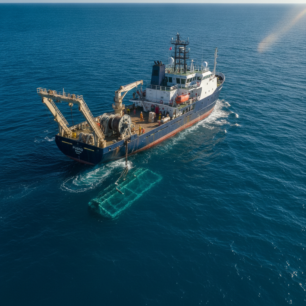
Scoping a deepwater site-characterisation campaign for FEED-ready ground models
Fugro's Timor-Leste award over 3,000m of water frames a wider client decision: how to scope geophysical and geotechnical work into a FEED-ready ground model.
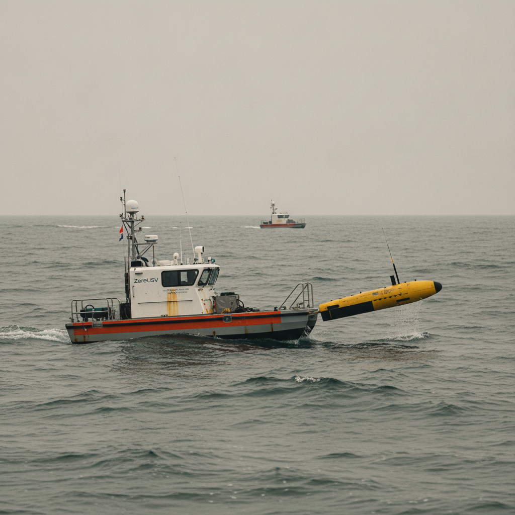
USV launch and recovery: reading the reliability threshold
USV launch and recovery (LARS) reliability, not launch, sets the threshold for designing crewed vessel days out of an uncrewed survey campaign.
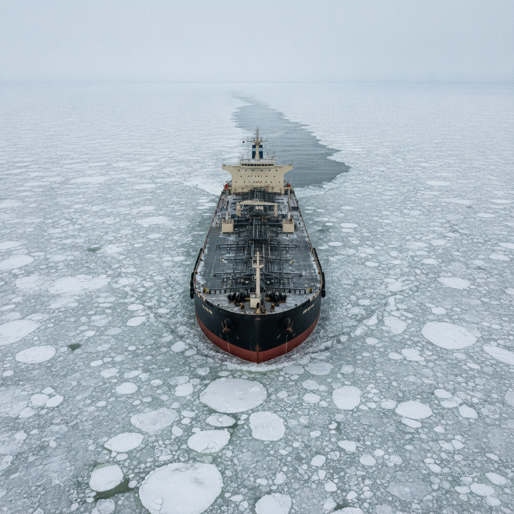
When does a non-ice-class tanker need an icebreaker? The shoulder-season decision
Drift ice, no icebreaker, a non-ice-class tanker on the berth window. How operators decide when unescorted transit is defensible – POLARIS, Baltic practice, ice advisors, and the metocean discipline the decision deserves.
Offshore Geomatics Foundation Certificate · October 2026
Turn reading into certified competence
Decisions like this one are easier to defend when the fundamentals behind them are certified, not assumed.
Early-access list gets 40% off at launch. No spam – the waitlist is only ever used for the certificate. What the certificate covers →