Executive Summary
Automated route optimisation for subsea pipelay produces precise, confident corridors – but only from the ground model it is fed. We analyse how survey-data defects (resolution, positioning, sparse geotechnics, mobile seabed) survive into an "optimal" route, why the QA chain rarely catches them, and how to specify survey and ground-model acceptance criteria backward from the engineering decisions the route actually depends on.
On this page6 sections
A routing paper that lands on the survey team’s desk
The September 2026 issue of the Journal of Pipeline Science and Engineering (Volume 6, Issue 5) carries a paper on automated route optimisation for subsea pipelay, authored by Yungen He, Lijie Zhang, Bohong Wang, Jing Huang, Bei Jiang, Ming Chen and Xiang Li. The subject is the algorithm: how to search a seabed model for the least-cost pipeline corridor under a set of constraints, and how to do it without a route engineer manually dragging a polyline across a chart for weeks.
That is worthwhile work. Route selection is a real optimisation problem with competing cost drivers – length, seabed intervention, span rectification, crossing count, curvature limits, geohazard avoidance. But an optimiser is a consumer of a ground model, not a producer of one. Its output inherits every property of its input, including the defects. Our interest here is the failure surface that automation exposes: what happens when a confident routing engine is handed survey data and a ground model that cannot support the decisions being made from them. That is where the money is lost, and it is a survey-data problem before it is an algorithm problem.
The failure mode: a precise route on an unproven seabed
The characteristic failure is not a crash or a wrong answer that looks wrong. It is a route that looks authoritative – smooth, curvature-compliant, span-minimised, plotted to the decimetre – laid over a seabed representation that never justified that precision. The optimiser treats the digital terrain model (DTM) and the attributed geotechnical layers as ground truth. It has no mechanism to distinguish a well-constrained cell from an interpolated guess. So it commits to the guess with the same confidence it commits to the fact.
The consequences show up long after route approval, and they are expensive:
- Free spans that were never in the model. DNV-RP-F105 span assessment depends on the along-route seabed profile at the length scale of the pipe’s dynamic response. If the DTM smooths a scarp, a boulder, or a narrow gully, the span appears and the rock-dump or span-support scope arrives as a variation order after the pipe is down.
- Upheaval and lateral buckling driven by profile the model did not resolve. DNV-RP-F110 global buckling behaviour is sensitive to seabed unevenness, out-of-straightness and cover. A route “optimised” for minimum trenching over a profile that was interpolated between sparse crossings can put the line into a buckling regime the design never accounted for.
- On-bottom stability shortfalls. DNV-RP-F109 lateral resistance depends on soil type and strength. Optimise a corridor across a seabed the model called sand where it is actually soft clay, and the stability and pipe-soil interaction assumptions (DNV-RP-F114) no longer hold.
- Trenchability and burial surprises. A plough or jet trencher meets boulders, cemented layers or buried channels the sub-bottom coverage never showed, and the burial-depth requirement for thermal or upheaval design is not achieved.
None of these is a routing error in the algorithmic sense. Each is a case of the optimiser faithfully executing on a seabed that does not exist in the resolution and certainty the route implies.
Chain of causation: where the model diverges from the seabed
The divergence between the ground model and the actual seabed accumulates through a chain of ordinary, individually defensible decisions.
Bathymetric resolution that the point density does not support. A gridded DTM at 0.5 m or 1 m cell size looks the same whether the soundings behind it were dense or thin. Multibeam coverage that satisfies a charting deliverable can still under-sample the small-wavelength features that govern span analysis. Interpolation then manufactures a smooth surface with no warning attached. The route engineer sees continuous terrain; the seabed has structure the survey never captured.
Positioning and vertical-datum error that the model does not carry. Absolute position uncertainty from the survey vehicle’s INS/USBL solution, residual sound-velocity refraction artefacts in the multibeam, tidal-reduction and datum errors – all of these blur where a feature actually is. A route defined to sub-metre horizontal precision over a DTM with a metre or more of absolute uncertainty is precise about the wrong place. The problem compounds when the lay vessel’s touchdown-monitoring positioning sits in a different geodetic frame or reduction than the route survey. As-designed and as-laid then disagree for reasons that have nothing to do with laying.
Geotechnical sampling too sparse for the geology. Route optimisers consume attributed soil layers – strength, friction, thermal conductivity, trenchability – but those attributes come from a handful of CPTs, boreholes or vibrocores interpolated across kilometres. Where the geology is uniform, sparse sampling is fine. Where it varies (channel fills, glacial tills, interbedded sands and clays), interpolation invents parameters the optimiser then treats as measured. The routing cost surface becomes confidently wrong exactly where the ground is most variable.
Sub-bottom and hazard coverage that misses the third dimension. Boulders below the seabed surface, shallow gas, palaeochannels and buried debris do not appear in bathymetry. They belong to the sub-bottom profiler and the magnetometer/gradiometer, whose penetration, line spacing and detection thresholds set what the model can contain. A corridor optimised on surface morphology alone routes straight through hazards the survey design excluded by geometry.
A mobile seabed that has moved since acquisition. In sand-wave fields, scour zones and mobile-sediment areas, the seabed the survey recorded is not the seabed the pipe will land on. Bedform migration between survey and lay can be metres per year. An optimiser has no concept of survey age; it routes on the DTM’s date as if it were today.
The common root cause beneath all five is that the ground model is treated as a deterministic deliverable rather than a spatially varying estimate with attached confidence. Automation removes the human who, drawing a route by hand, instinctively distrusts the smooth patch between two survey lines.
Why the defect survives to the lay barge
Detection should catch these before route approval. In practice the QA chain has structural gaps that let a flawed model through with a clean sign-off.
The interface between acquisition, processing, ground-model building and route engineering is where uncertainty goes to die. Each handover passes a cleaner-looking product than it received. Raw uncertainty from the positioning and sounding solution is real and quantified; by the time it reaches the optimiser as a gridded surface with soil attributes, the uncertainty has been stripped and only the best estimate survives. No cell in the model says “interpolated, low confidence”. The optimiser cannot avoid a hazard it was never told might be there.
Acceptance criteria are written against the wrong yardstick. Survey deliverables are commonly signed off against hydrographic standards such as IHO S-44 Edition 6, or against generic client survey specifications. Those set positioning and coverage targets for charting and general engineering, not the resolution and certainty that a specific route decision demands. A dataset can pass S-44 Order 1a and still be inadequate for a DNV-RP-F105 span assessment at the wavelength that matters. Passing the standard is taken as fitness for purpose, and it is not the same thing.
No sensitivity analysis on the routing output. The optimiser returns a single “optimal” corridor. Rarely is it re-run with perturbed inputs – DTM shifted within its stated vertical uncertainty, soil parameters varied across their credible range, feature positions moved by the positioning error budget. Without that, no one knows whether the optimum is stable or whether a decimetre of terrain error swings the least-cost route into a different valley entirely. A brittle optimum is a warning the process never surfaces.
Verification against ground truth is thin or skipped. The confident-looking deliverable discourages the close-range ROV visual verification of critical segments, crossings and suspect features that would expose the interpolation. When budget is tight, the verification survey is the first casualty, precisely because the model already looks finished.
What it teaches: specify backward from the decision
The transferable lesson is that survey and ground-model requirements must be derived from the engineering decisions they will feed, not from a generic standard applied out of habit. The route optimiser makes the dependency worse, because it consumes the model at face value and at machine speed. Get the input specification right and automation is a genuine gain; get it wrong and automation industrialises the error.
Concretely, the decisions drive the specification like this. Free-span assessment sets the along-route vertical accuracy and horizontal resolution – you specify the DTM to resolve the span wavelengths the design is sensitive to, not to a round number. Global-buckling and out-of-straightness assessment set the profile fidelity and the survey-to-lay positioning reconciliation. On-bottom stability and trenchability set the geotechnical sampling density, which must follow geological variability rather than a fixed line spacing. Hazard avoidance sets sub-bottom penetration, line spacing and magnetometer detection thresholds. Each of these is a number the route engineer can defend, and each should appear in the survey scope with the reason attached.
The other lesson is that the model must carry its own uncertainty into the optimiser. A ground model that attributes confidence per cell – well-constrained by sampling, versus interpolated, versus extrapolated – lets the routing cost surface penalise uncertainty directly. The optimum then prefers corridors the survey actually proved, and flags where it is betting on a guess. That is a different deliverable from the single deterministic surface most projects still build.
Preventing the optimised failure
The safeguards below are specific and testable by the survey and engineering functions that own this risk.
- Write the survey specification as a requirements trace. For each route-critical assessment (RP-F105 spans, RP-F110 buckling, RP-F109 stability, RP-F114 pipe-soil, trenchability), state the DTM resolution, vertical/horizontal accuracy, geotechnical sampling density and sub-bottom coverage it needs, and the reason. Reject deliverables that meet IHO S-44 but not the traced requirement. Reference IOGP site-survey guidance for the acquisition scope, but let the design set the tolerances.
- Attribute uncertainty to every layer of the ground model and feed it to the optimiser. No un-flagged interpolation. Where soil parameters are interpolated across variable geology, mark those cells low-confidence and let the routing cost reflect it. If the optimiser cannot accept a per-cell confidence field, that is a limitation to fix before it drives a route.
- Run the optimiser as a sensitivity study, not a single shot. Perturb the DTM within its stated vertical uncertainty, vary soil parameters across their credible range, and shift feature positions by the positioning error budget. If the least-cost corridor is unstable under those perturbations, the “optimum” is not decision-grade and needs more survey, not more computation.
- Reconcile survey and lay positioning in one geodetic frame before route freeze. Confirm datum, projection, tidal reduction and sound-velocity QC are consistent between the route survey and the lay vessel’s touchdown monitoring. A mismatch here guarantees an as-designed to as-laid discrepancy that will be misattributed to laying.
- Re-survey mobile-seabed sections close to lay and check bedform migration. Where sand waves or scour are present, treat survey age as a hard constraint. Compare the pre-lay survey against the route-design survey and re-run affected route segments if the seabed has moved beyond the tolerance the span and stability work assumed.
- Verify critical segments and crossings with close-range ROV inspection before committing. Ground-truth the interpolated patches, the suspect features and every crossing. Decide up front whether to own that acquisition capability or contract it, a trade we have examined in the context of choosing between buying a survey asset and buying the result.
- Close the loop with the as-laid record. The post-lay configuration survey is the audit of everything above. Specify it to resolve what the buckling and span assessments actually need – the point of what an out-of-straightness survey has to demonstrate – and use the discrepancies against the design route to recalibrate the next project’s ground-model assumptions.
Automated route optimisation earns its place when the ground model beneath it is honest about what it knows and what it guessed. The engineering work that makes automation safe is not in the search algorithm. It is in specifying, verifying and uncertainty-attributing the survey data so that a machine optimising at face value is optimising over a seabed that is genuinely there.
Published by
Hydrographic Methods Committee
Bathymetry, Multibeam & Seabed Mapping
An independent review committee focused on hydrographic survey methodology, IHO standards interpretation, and seabed mapping best practices for offshore and coastal projects.
Read next

The DP incidents you never hear about: why concealment still pays
DP position-loss incidents keep repeating not because the technology is immature, but because concealing them is still rational. A failure analysis of the industry's broken learning loop – and what operators can do about it.

ASOG and DP drift-off: why crews bypass the guidelines
ASOG, IMCA M 220 and DP drift-off: why crews bypass the activity-specific guidelines they helped write, documented in IMCA DP event bulletins.
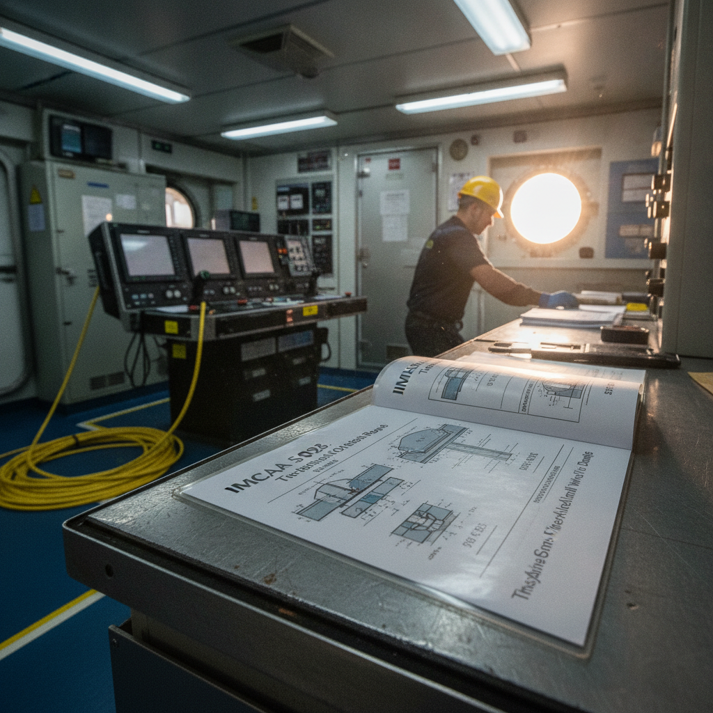
IMCA S 026, unpacked: what an out-of-straightness survey actually requires
IMCA S 026 out-of-straightness survey guidance, unpacked: the checks, error budget, deliverables and QC it actually specifies for rigid subsea pipelines – and where it leaves the numbers to your project procedures.
Offshore Geomatics Foundation Certificate · October 2026
Turn reading into certified competence
Most of the failures we analyse trace back to fundamentals nobody verified. The Foundation Certificate is a structured way to close exactly those gaps.
Early-access list gets 40% off at launch. No spam – the waitlist is only ever used for the certificate. What the certificate covers →