Executive Summary
Every method used to survey free spans on subsea pipelines gives you the span length; almost none gives you the gap beneath the pipe – the very number a vortex-induced-vibration fatigue assessment turns on. We review the full toolkit, organised by what each method actually resolves, and argue that the industry measures length well and the gap poorly. Before the instruments, one variable sets the ceiling on what is measurable at all: how the pipeline sits in the seabed. We rank the methods for resolving the gap – from coarse hull multibeam, through ROV profiling sonar, to the most reliable, ROV video lit from the far side of the pipe – and close with how to match the method to the integrity question under DNV-RP-F105.
A free span is simple to define and deceptively hard to measure. Where a subsea pipeline lifts off the seabed – over a sand wave, an erosion scour, a rock outcrop – two numbers decide whether that span is a line in a report or a fatigue problem: how long it is, and how high the pipe sits above the seabed. The length is easy; almost any survey method gives it to you. The gap is not, and the gap is the number the engineering actually turns on.
That asymmetry is the subject of this piece. We set out the methods used to determine free-span parameters – all of them – but we organise them by what they actually resolve, because the honest position is that the industry measures span length well and span height poorly, and then feeds both into a fatigue assessment that is more sensitive to the one it measures worst. And before any instrument, there is a variable that decides how measurable a span is at all: how the pipeline sits in the seabed. The seabed decides before the instrument does.
This is written for the people who specify and read these surveys – survey and geomatics managers, and the integrity engineers who consume the results – rather than for the ROV pilots who already know the cameras tell the truth.
Two measurements wearing one name: length and the gap
Length and gap are not two readings of the same thing; they feed different parts of the physics. Span length sets the natural frequency of the free section: the longer the span, the lower its natural frequency, and the closer that frequency sits to the excitation from current and waves. The gap – the clearance between the pipe and the seabed – sets the flow regime around the pipe, and that is what governs whether the pipe sheds vortices at all.
This is where the gap stops being a “nice to have.” In free-span assessment to DNV-RP-F105, the governing recommended practice for free spanning pipelines, the gap drives the flow regime around the pipe through the ratio of gap to pipe diameter, e/D. The standard itself sets no cut-off on the gap; it corrects the vortex-shedding onset velocity and the response amplitude continuously for seabed proximity, and that correction bites hardest at the smallest gaps – proximity matters more, not less, as the pipe nears the seabed. The wider vortex-induced-vibration literature adds only a rough floor: below something like a third of a diameter of clearance, the wall largely suppresses shedding. Either way the consequence runs the wrong way for comfort – it is exactly at the small gaps, where the assessment is most sensitive, that a modest error in the measured height most changes the predicted fatigue response. The gap is a primary input to the fatigue limit state, and it is the input we measure worst.
Two honest caveats keep that in proportion. Length and gap are what the survey delivers, but the assessment also consumes the soil stiffness at the span shoulders and the flow regime over the span, so the measured geometry is necessary, not sufficient. The survey’s job is therefore narrow and exact: hand the assessment a length, and above all a gap, it can trust.
All of this sits, in practice, inside an integrity-management programme of the kind DNV-RP-F116 describes: spans are found, assessed, and either accepted, monitored, or remediated. Every one of those decisions inherits the quality of the original measurement. A coarse gap does not stay a survey problem; it becomes an engineering decision made on a soft number.
The seabed decides before the instrument does
Before choosing an instrument, look at how the pipe sits in the seabed, because that – more than the sensor – sets the ceiling on what can be measured. Three cases bound the problem.
A pipe resting proud on a flat seabed is the easy one. There is a clean line where the pipe leaves the bottom, a clear void beneath it, and a well-defined surface to measure the gap against. Almost every method performs near its best here.
A partially embedded or trenched pipe is harder, and the difficulty is conceptual before it is instrumental: where is “the seabed” you are measuring the gap to? The reference surface under the pipe is ambiguous, the touchdown is gradual rather than sharp, and the number you report depends on a definition as much as on a sensor.
The hardest case is a pipe embedded with a void retained beneath it – a real gap, concealed under the embedment. Here a span exists, with all its fatigue implications, but it is invisible to anything that works from above the seabed. Wide-area acoustic sees a buried pipe; a camera sees no gap because it cannot get light into one it cannot reach. The span is real and the standard methods are blind to it.
The lesson is uncomfortable and rarely stated: a method that is excellent over a proud pipe on flat ground can be near-useless over a partially buried pipe with a concealed void. Read the embedment geometry first, then choose the tool – not the other way round.
Finding the span: wide-area acoustic, and what it cannot tell you
The wide-area acoustic methods are how spans are found and how length is measured, and they are very good at both. A hull- or vessel-mounted multibeam echosounder maps bathymetry efficiently over kilometres, fixes the pipeline route, and resolves where the pipe lifts off and touches down – which is to say, the span length – reliably. Side-scan sonar finds spans even faster, reading the acoustic shadow a proud pipe throws across the seabed; it is an excellent screening tool.
What they cannot do is give you the gap. At survey altitude the multibeam beam footprint averages across the pipe and seabed, the region directly beneath the pipe is shadowed from the beams, and the vertical resolution of a small clearance is simply not there. There is a subtler trap, too: a multibeam measures the pipe’s crown, so the clearance underneath is not measured but derived – seabed level minus the pipe’s known outer diameter – which compounds the error in both surfaces. And “coarse” is the wrong vocabulary anyway: survey quality belongs in the language of uncertainty – a total-propagated-uncertainty budget, in the spirit of the IHO S-44 accuracy orders, even where free-span work is specified to a project or IMCA tolerance rather than to S-44 directly – and a derived, partly occluded gap rarely carries the uncertainty the length comfortably does. Side-scan is worse for height: it is qualitative on the gap, and its shadow story only holds when the pipe runs above a flat seabed. Over irregular or embedded geometry the shadow breaks down and side-scan becomes coarse. Interferometric and bathymetric side-scan add some height information but remain wide-area instruments with wide-area limits. The one wide-area method that narrows the problem is an autonomous underwater vehicle flying the same multibeam at a low, steady altitude: closer to the seabed than any hull, it both covers ground efficiently and tightens the bathymetry, narrowing – though never closing – the gap-resolution problem, which is why AUV survey has become the workhorse for long pipeline routes.
So treat the wide-area acoustic tier for what it is: the way to find spans and measure their length. Do not ask it for the gap, and do not let it answer the gap by default just because it is the data you already have.
The hard part: resolving the gap
To measure the gap you have to go closer, and there is a clear hierarchy in how well the close-range methods do it.
An ROV carrying a dual-head profiling echosounder is already a step up from hull multibeam: shorter range, a finer footprint, and a genuine cross-profile of pipe and seabed. It resolves the gap better – but it is still acoustic, and still limited directly under the pipe where the geometry matters most.
The optical close-range methods go further where line of sight allows. Subsea laser and structured-light scanners, and photogrammetry or SLAM reconstructions, build near-field three-dimensional geometry at millimetre-class resolution, and over an accessible gap they capture it well.
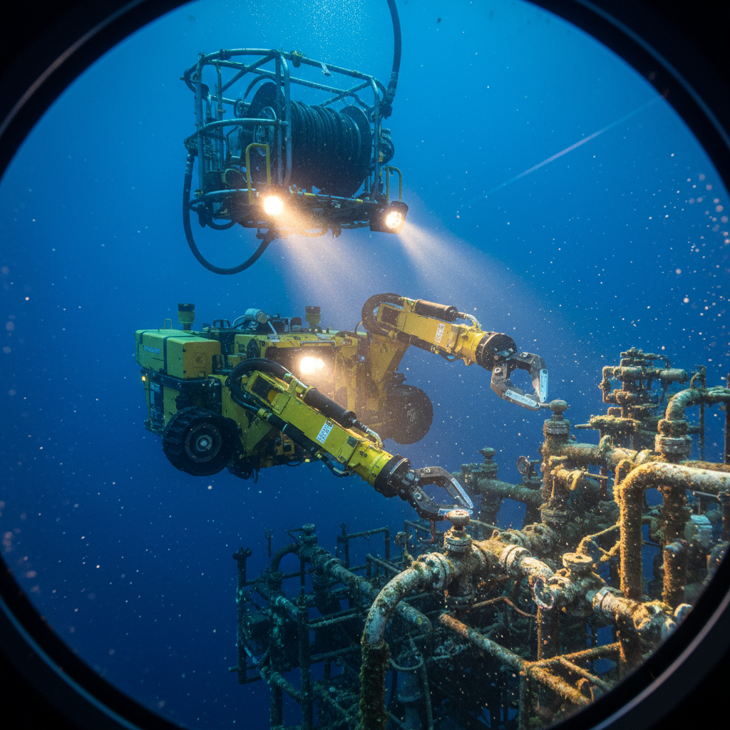
But the most practical and most reliable gap measurement is deceptively simple, and it is optical in the oldest sense: ROV video with directed lighting. The technique that beats the rest is to place the camera on one side of the pipe and a lamp on the other, so the pipe is silhouetted against the backlight and the clearance between pipe and seabed reads as a clean band of light. It is a long-established inspection practice rather than a field improvisation, and it works precisely because it sidesteps acoustics. Backlit that way, the gap is unambiguous to the eye, and – with a scale or known standoff in frame – to measurement too, in a way no top-down acoustic return can match. That puts the height-quality hierarchy in plain order: hull multibeam is the coarsest, the ROV profiling sonar is better, and ROV video lit from the far side of the pipe is the most reliable, for the height and often for the length as well.
The catch returns to the master variable. Backlighting is superb over a proud pipe; over a partially embedded pipe with a concealed void, even the camera cannot light a gap it cannot reach. The best instrument in the inventory is still bounded by how the pipe sits in the seabed. And there is a second catch, environmental rather than geometric: every optical method here – laser, photogrammetry, and the prized backlit video – depends on water clarity. In turbid water the silhouette dissolves and the hierarchy inverts, because the acoustic methods see through what light cannot.
The pipe’s own story, and the clock
Two more families round out the toolkit, and both matter precisely where the direct methods struggle.
The pipe can be made to report its own geometry. In-line inspection with an inertial measurement unit maps the pipeline’s centreline – its out-of-straightness – from the inside; combined with a seabed survey, it infers spans from the shape of the pipe rather than the shape of the bottom, which is valuable exactly where the seabed reference is ambiguous. Pipe trackers and electromagnetic locators add position and depth of burial. And the sub-bottom profiler sees beneath the seabed, the one way to distinguish a buried pipe from a spanning one and to find the concealed void that defeats everything working from above – though in practice the void is often inferred by reading the sub-bottom and the inertial pipe geometry together, since imaging it cleanly is hard.
Then there is the time dimension. For known spans held under a fatigue watch, acoustic span and vibration monitoring sensors – strain gauges and accelerometers logging the response over time – measure what the assessment is trying to predict, and close the loop on DNV-RP-F105 by replacing an estimated response with an observed one. Trending a span across repeat surveys is its own positioning problem: you have to relocate the same metre of pipe, which leans on USBL or inertial navigation as much as on the gap sensor.
Choosing the method to fit the question
The decision rule falls out of everything above. Match the method to the parameter and to the integrity question, in that order. The toolkit, ranked by what each method actually resolves, looks like this:
| Method | Finds the span? | Span length | Gap (height) | Key limit |
|---|---|---|---|---|
| Hull / vessel multibeam | yes, efficient | reliable | weak – crown only, gap derived | footprint, occlusion, sound-velocity at altitude |
| Side-scan sonar | yes, fast screen | approximate | qualitative | needs a flat reference seabed |
| AUV multibeam (low altitude) | yes, efficient | reliable | better than hull, still acoustic | no read of the under-pipe void |
| ROV dual-head profiling sonar | yes | reliable | good cross-profile | acoustic limit directly under the pipe |
| Subsea laser / structured light | close-range only | yes | strong, millimetre-class and metric | water clarity; needs scale and registration |
| ROV video, backlit | close-range only | yes | most reliable read | water clarity; needs a scale to be metric |
| In-line inspection (inertial) | from pipe shape | yes | inferred | piggable line; pairs with a seabed survey |
| Sub-bottom profiler | buried pipe and void | – | – | the only look beneath; hard to image cleanly |
| Span / VIV monitoring | known spans | – | measures response, not geometry | time-domain; needs the geometry to interpret |
Read the seabed-embedment geometry first, because it tells you whether the gap is measurable from above at all, and whether you need sub-bottom or pipe-geometry methods to see a void the cameras and sonars will miss. Screen wide with multibeam and side-scan to find the spans and measure their length. Then confirm the gap close-range – ROV video with backlighting, or profiling sonar and laser where access allows – on every span that feeds a fatigue case.
The failure to avoid is the convenient one: letting a hull-multibeam gap number, coarse by construction, drive a vortex-induced-vibration decision under DNV-RP-F105 – when the assessment is most sensitive to exactly that number, at exactly the small gaps where multibeam is weakest. The instruments are not interchangeable, and the cheapest answer, a single wide-area pass, is precisely the one that under-serves the parameter the engineering cares about most.
The length is easy; the gap is not. The discipline of a good free-span survey is deciding, before anyone mobilises, which question you are answering – screening a route, or defending a fatigue life – and therefore which method has to be in the water, and how close to the pipe it has to get.