Executive Summary
IMCA's guidance on ROV operations during diving has received a major review and rewording in Rev. 1, its first substantive revision since 2014. The document's structure assigns clear decision rights, links control measures to ROV power rating, and adds explicit sections on emergency diver recovery and joint drills. The binding constraint on site is whether the dive and ROV teams can show a shared, tested control regime. Supervisors should gap-analyse their bridging documents, hazard registers and drill records against the new text before the next mobilisation.
On this page14 sections
- What the revision changes, and what it does not
- The architecture of control: decision rights first
- Power rating as the organising parameter
- Electrical, navigation and vessel interface hazards
- Electrical
- Navigation and positioning
- Vessel and platform interface
- Gaps and gotchas in applying the guidance
- 1. Two contractors, one hazard
- 2. Power ratings and new vehicle types
- 3. “Safe distance” without a number
- 4. ROVs in emergency diver recovery
- 5. Familiarisation that counts as an attendance check
- What supervisors and project engineers should do before the next mobilisation
What the revision changes, and what it does not
IMCA has published Rev. 1 of its guidance on remotely operated vehicle intervention during diving operations, described in the revision history as a “major review and rewording”. The document was first published in October 2014. Its intermediate revisions were all minor: terminology amendments in January 2020, amendments to item 11 in April 2021, and a quality check with a document map added in December 2023 that made no change to content. Rev. 1 is therefore the first substantive rework of the text since its original publication.
The current revision sets out its purpose as addressing the hazards that arise when divers and ROVs work in the same underwater space. It provides a framework covering planning, risk assessment, communications, operational controls, responsibilities and emergency preparedness. The contents list includes ROV power ratings, separate control measures for safe interaction and for diver-ROV operations, ROV team requirements, physical protection of personnel, familiarisation, the vessel or platform interface, ROV configuration, navigation, location and positioning, electrical considerations, the use of ROVs in emergency diver recovery, and joint drills with collaborative pre-planning. Appendix A summarises the changes. The contents list alone does not show which sections are new and which were carried over from the earlier text.
This article is based on the document’s published summary, contents list and revision history; we do not reproduce or characterise clause wording. A rewording of this scale changes emphasis in ways a summary cannot capture, so supervisors and project engineers should read Appendix A against their current procedures. Our aim is to set out the engineering logic we think the subjects in that contents list call for, and to identify where that logic will meet resistance on site. Where we describe practice below, it is our recommendation. It is not a statement of the document’s provisions.
The architecture of control: decision rights first
Our starting point is a principle every experienced diving supervisor will recognise from IMCA D 014. While divers are in the water, the diving supervisor holds authority over everything that affects their safety, and that includes an ROV operating nearby. The ROV supervisor remains responsible for the vehicle, its tether management and its crew, but in our view that responsibility has to sit beneath the diving supervisor’s authority whenever a diver is in the water. IMCA R 004 governs the ROV side in isolation. This document deals with the interface between the two.
The contents list does not tell us how the guidance allocates decision rights clause by clause. Based on established practice under IMCA D 014 and common bridging-document arrangements, we suggest the following split as a baseline to test against the full text:
- Entry into the diver’s working area. The ROV enters only on the diving supervisor’s explicit instruction and leaves on instruction. Pilot judgement does not substitute for that instruction, however experienced the pilot.
- Stopping. Any party with a safety concern can call a stop. Restarting needs the diving supervisor’s agreement and confirmation from the ROV supervisor that the vehicle is in a safe state.
- Vehicle configuration. The ROV supervisor owns the technical configuration: thruster guarding, manipulator state, tooling isolation and auto-functions. The diving supervisor is told, before the dive, what that configuration is and how it changes during the task.
- Emergency use. Any ROV role in diver recovery is fixed in the emergency plan before the dive. It cannot be improvised once something has gone wrong.
The document gives “Responsibilities” its own section, separate from “Operational procedures”, and we think that separation matters. Bridging documents often state that the diving supervisor is “in overall control” and stop there. That is correct, but it does not tell the ROV pilot what to do between losing voice comms with dive control and regaining them. A responsibilities section that is fit for purpose assigns a default safe action to each role for each foreseeable loss of control or communication.
Power rating as the organising parameter
We think a headline section on ROV power rating reflects sound engineering. The hazard an ROV presents to a diver scales with the energy it can deliver through thruster wash and thrust, mass and momentum, manipulator force and the hydraulic or electrical power behind its tooling. A small electric observation vehicle and a heavy work-class vehicle with high-pressure hydraulics need different interaction rules. Whether the guidance itself grades control measures by power needs checking against the full text; grading them by energy avoids two failure modes. One is applying work-class restrictions to an inspection vehicle, which pushes crews to treat the whole regime as bureaucratic. The other is giving a work-class vehicle the freedom suited to a small observation unit.
In our risk assessments, several mechanisms dominate.
Thruster wash and suction. A diver close to a thruster is exposed to entrainment and to the force of the wash, and the umbilical can be drawn into an unguarded thruster. Guarding cuts down the entanglement path but does nothing about the hydrodynamic force. The controls for that are distance and thrust limits set in the vehicle software, verified on deck and recorded.
Tether and umbilical interaction. Tether and umbilical interaction is widely recognised as a significant entanglement hazard in diver-ROV operations. Two flexible members deployed from one surface asset or two will cross unless their geometry is planned. That geometry includes the TMS deployment point relative to the bell or basket, the guide wires and clump weight, and each member’s excursion envelope under the prevailing current. Plan it on a scaled drawing during pre-planning rather than leaving it to resolve itself in the water.
Manipulator and tooling energy. A hydraulic manipulator can exert crushing force well beyond what a diver can resist, and torque tools and cutters carry their own stored energy. We treat the configuration section as the place to settle, before each dive, whether functions are isolated, pressure-reduced or parked, and how the diving supervisor will confirm that state on the ROV video.
Automatic functions. Auto-depth, auto-heading and station-keeping can move the vehicle without pilot input. The agreed diver-proximity configuration should state which auto-functions are permitted and what the vehicle does when an aiding source fails, for example DVL dropout causing station-keep to drift or hunt.
Electrical, navigation and vessel interface hazards
The separate sections on electrical considerations, navigation and positioning, and the vessel or platform interface cover three hazard groups that generic SIMOPS risk assessments can miss.
Electrical
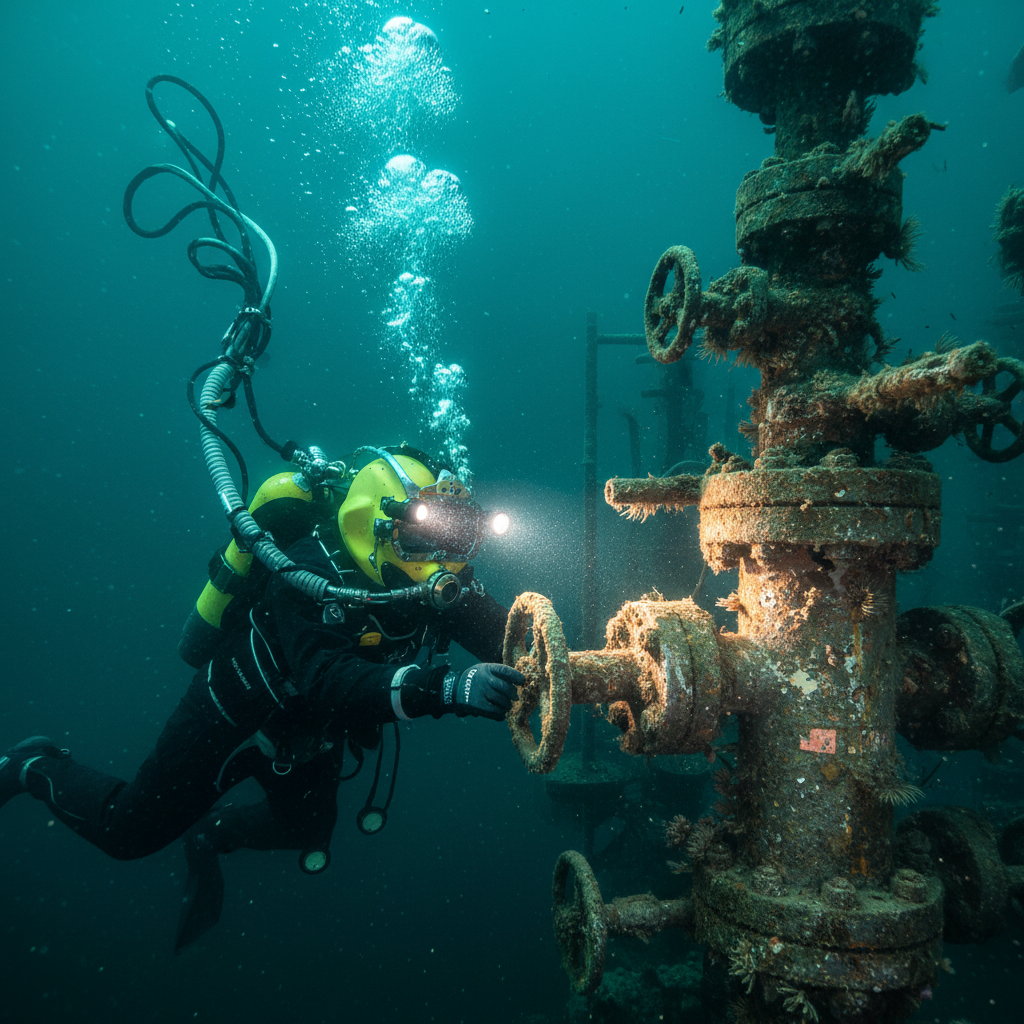
For a high-voltage work-class system, the diver hazard is current leaking into the water near the diver through failed insulation. The controls are line insulation monitoring, ground fault detection with defined trip behaviour, and evidence that the protection has been tested. Failure modes inside pressure housings, battery systems in particular, are a separate subject, and we cover the long-term field record of battery packs in subsea pressure housings elsewhere. They become more significant as electric and battery-backed vehicles spread.
Navigation and positioning
A diver and an ROV tracked on separate systems, in separate reference frames, on separate displays, are not deconflicted. The minimum is a common positioning picture. Diver and vehicle positions should be shown in the same frame, ideally from the same USBL system with a common calibration, and visible in both dive control and ROV control. Where different systems are used, the procedure should include a cross-check against a known fixed reference, and any persistent offset should be resolved before the ROV moves into the diver’s area. If separation is defined in metres, positioning error has to be part of that distance. A stand-off smaller than the combined uncertainty of the two fixes provides no real separation.
Vessel and platform interface
When the ROV deploys from the same DP vessel as the divers, the IMCA M 103 and IMCA D 010 frameworks already cover the main vessel failure modes. The diving-specific issue is how DP alert status maps to ROV actions. The ROV procedure needs a defined response for each ASOG condition, written alongside the diver recall instructions. A drift-off with a deployed TMS and tether is a separate entanglement event developing at the same time as the bell or basket hazard. The gap between documented ASOG responses and actual crew behaviour is a familiar one, as our analysis of why crews bypass ASOG guidance during drift-off discusses. When the ROV works from a second vessel or a platform, the two surface assets can move independently, and the interface plan must state which asset’s status change triggers which recall.
Gaps and gotchas in applying the guidance
The subjects the document covers are the right ones. The difficulties tend to arise where any framework of this kind meets real contracting arrangements and equipment.
1. Two contractors, one hazard
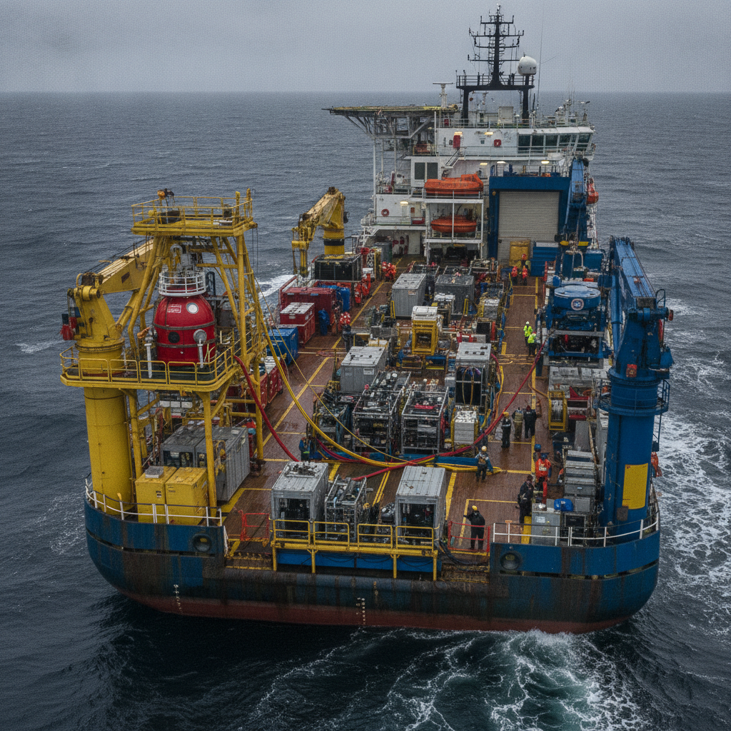
The guidance has a responsibilities section, but no guidance can settle the commercial arrangements underneath the roles. When diving and ROV scopes are let separately, each contractor’s management system governs its own personnel, and the bridging document becomes the only instrument holding the interface together. The weak point is usually the authority to stop and restart work, rather than the authority to direct it. Supervisors under separate contracts should check that the bridging document gives the diving supervisor operational authority over the ROV crew that the ROV contractor’s own procedures recognise. We cover the governance issues in more depth in our piece on running combined subsea operations with separately contracted parties.
2. Power ratings and new vehicle types
Any classification based on power rating assumes that a vehicle’s power figure is a fair proxy for its hazard. Electric work-class vehicles, hybrid systems and vehicles fitted with high-thrust electric tooling complicate that assumption. A vehicle with modest installed power can carry a tool with substantial stored energy. Our recommendation is to assess on the worst credible energy source on the vehicle as configured for the task, not on its nominal rating.
3. “Safe distance” without a number
Risk assessments often record separation as “a safe distance” or “as agreed between supervisors”. That wording cannot be tested and does not survive a crew change; recommendation 3 below sets out the alternative.
4. ROVs in emergency diver recovery
The emergency recovery section concerns a capability operators may already rely on informally. In our experience that includes lighting, observation of an incapacitated diver, umbilical tracing and sometimes equipment delivery. The risk is that this capability ends up in the critical path of the rescue plan without having been demonstrated. An ROV that has never practised approaching a motionless diver with the standby diver deployed can hinder the rescue it is meant to support. Any ROV task in the emergency plan should be specific, carry a stated withdrawal condition, and add to the surface team’s capacity rather than divert it.
5. Familiarisation that counts as an attendance check
Divers need to know where the ROV’s thrusters, guarding, manipulators and tooling are, and how it behaves on power loss. A dive shack briefing does not achieve that; recommendation 9 below does.
What supervisors and project engineers should do before the next mobilisation
These are our recommendations. We have written each step so that it can be verified at project level, with as little dependence on client or contractor-wide change as possible.
-
Run a clause-by-clause gap analysis against Rev. 1. Use Appendix A as the index. For each change, record whether your diving procedures, ROV procedures and project bridging document already comply, need amendment, or need a client-approved deviation. Close the gap analysis before the project hazard identification and risk assessment (HIRA) is signed.
-
Write the decision-rights matrix as a table. For each mode (pre-dive, diver in transit, diver at worksite, diver recall, emergency), give the authority to move the ROV, to stop, to restart, and the default action on loss of comms. Have both supervisors sign it at each crew change.
-
Define a numerical stand-off for each ROV task. Base it on vehicle stopping distance, combined USBL uncertainty and umbilical excursion, and record the calculation in the task risk assessment. Do not accept “safe distance” as a hazard register entry.
-
Verify the all-stop at the start of every shift. Dive control calls the all-stop, the ROV supervisor confirms from console telemetry that thruster output is zero, and dive control verifies it on the ROV video feed (or a telemetry repeater, where fitted). Log the call-to-stop time. Agree a maximum with both supervisors at mobilisation, and investigate any shift where it is exceeded or the times trend upwards.
-
Document ROV configuration for diver proximity. Before each dive phase, list the guarded thrusters, thrust limits, isolated manipulator and tooling functions and enabled auto-functions. The diving supervisor confirms that state against the ROV video before clearing entry.
-
Make electrical protection a pre-dive hold point. Insulation monitoring active, ground fault trip tested within the project-defined interval, and the result logged and shown to dive control before the first diver leaves the surface.
-
Unify the positioning picture. Show diver and ROV positions in one frame in both control rooms. Where two systems are in use, cross-check against a fixed seabed reference before each dive, and do not allow ROV entry until any offset is within a tolerance derived from the combined positioning uncertainty.
-
Drill the ROV’s emergency role before operations start. Run at least one joint drill before the first dive with ROV support and repeat it at each crew change, covering the specific ROV tasks in the emergency plan. Record which tasks were demonstrated; remove any that were not.
-
Record diver familiarisation individually. Each diver completes a deck walk-around of the specific vehicle with the ROV supervisor, recorded in the dive log, and repeats it whenever the vehicle is changed or reconfigured.
We recommend starting the gap analysis against the revision promptly. In our view, three principles should anchor how teams apply it: the diving supervisor’s authority, control measures matched to the vehicle’s hazard energy, and a single shared picture of where both the diver and the vehicle are. Rev. 1 is the reference against which teams should check their procedures and show that those principles are applied in practice on the next job.
Based on: Remotely operated vehicle intervention during diving operations – IMCA technical library
Published by
Diving & Subsea Operations Panel
Commercial Diving, Life Support & IMCA Standards
An expert panel reviewing commercial and saturation diving operations, life support systems, IMCA diving standards, and subsea intervention safety practices.
Read next
Battery packs in pressure housings: field lessons from three decades
IMCA D 002 on battery packs in pressure housings: thermal runaway, housing design, lithium-ion risk and emergency response for subsea systems.
Separately contracted, same deck: governing combined subsea operations
Two subsea contractors on a third party's vessel, each contracted only to the operator and to no one else aboard. The gap left by the missing contract between them – and the machinery that has to fill it before anyone gets in the water.
IMCA S 026, unpacked: what an out-of-straightness survey actually requires
IMCA S 026 out-of-straightness survey guidance, unpacked: the checks, error budget, deliverables and QC it actually specifies for rigid subsea pipelines – and where it leaves the numbers to your project procedures.
Offshore Geomatics Foundation Certificate · October 2026
Turn reading into certified competence
You have just read what a standard actually requires – and where it stops. The Foundation Certificate exists to prove you can work with that distinction.
Early-access list gets 40% off at launch. No spam – the waitlist is only ever used for the certificate. What the certificate covers →