Executive Summary
Site investigation for a hot-tap or tie-in can put a drill string and seabed frame in critical proximity to a live pipeline. A spoof that jumps the position is usually rejected by the DP's own tests; one that drags it slowly is not. On the common reference set of two GNSS receivers and one acoustic system, the receivers move together, the DP rejects the honest acoustic, raises an alarm that points at the wrong sensor, and drives the vessel off station in a direction the spoofer chooses. We set out what the operator should require: substitution first; non-GNSS references of different principles governing inside the critical zone; the offset confirmed against the pipe itself; an ASOG that decides which sensor is lying from the one reference no spoofer can move, the borehole, and settles its release decision in advance; the operator's own consequence controls; and approval of that ASOG by an independent DP specialist with no stake in the schedule.
On this page16 sections
- What a drive-off does beside a live line
- What drives the risk
- How a DP system is persuaded to drive itself off station
- Why the equipment class gives false comfort
- The honest reference is not always honest
- The guideline most specifications still cite
- Jack-ups and fixed platforms
- Where the decision goes wrong
- 1. Treating DP-2 as protection against spoofing
- 2. Calibrating the acoustic array with the system it is meant to check
- 3. Letting the project merely acknowledge the ASOG
- 4. Placing jack-up legs on satellite positions
- Where the gap is most likely to open
- How to take the risk to ALARP
- The contractor’s side of the table
- What goes in the scope
Before a hot-tap or a subsea tie-in, someone has to know what the seabed will do under the new structure. A tee on a mudmat usually needs soil data to one or two mudmat widths, which seabed cone penetration tests (CPT) and cores can generally provide. When the design is piled, the required depth exceeds what a seabed rig can push, or a dense layer stops the cone, a geotechnical vessel lands a seabed frame and drills. The tie-in design fixes where the foundations sit; the geotechnical designer decides how close to them, and to the pipe, the investigation must go. Some positions end up in critical proximity to a line still carrying hydrocarbons under pressure.
What has changed is the sky. In several enclosed and semi-enclosed seas bordering areas of military activity, interference with global navigation satellite systems (GNSS) is now a working condition, and IMCA Information Note IN 1730 calls it routine in some regions. The operator, the company that owns the pipeline and lets the contract, is asked through the representative who signs the proximity permit to accept that a vessel on dynamic positioning (DP) will stay where it says it is for the day or more a borehole can take. The comfort offered is the equipment class: DP class 2 (DP-2), three position references on at least two principles, activity-specific operating guidelines (ASOG), and a failure modes and effects analysis (FMEA) proven on trials. All of it was built against one component, or one reference, going wrong. None of it was built against every satellite reference going wrong the same way at once.
Jamming is usually loud: receivers lose lock, alarms sound, GNSS drops out. A spoof that jumps the position by kilometres is usually loud too, because the DP rejects both receivers at once. The dangerous case is a spoof that drags the position slowly and coherently, below the limits the DP uses to reject a bad reference. That is the one that moves the hull while the display shows it on target.
What follows is the reasoning. The conditions it leads to are also set out as an ASOG spoofing readiness checklist to work through against your own ASOG, trial records and bridging document.
What a drive-off does beside a live line
Inside the critical zone, the distance from the line within which the vessel’s worst credible excursion could bring the string, the frame or anything dropped onto it (sized below), a DP excursion becomes a pipeline integrity event in four ways.
The borehole starts in the wrong place. If the position is false at set-up, the frame lands below a hull whose true position nobody knows: possibly on an exposed pipe or its rock cover; on a buried line, the bit or the cone can find the pipe itself.
The vessel moves while the string is in the ground. With the frame clamp closed for sampling or testing, string and frame act as one, and heave compensation removes vertical motion only. The bit stays put; the frame stays put only while its sliding resistance exceeds the load the bending string puts on the clamp. The string gives first, bending, bearing on the moonpool and possibly failing; then the lift wire and umbilical pull the frame once their slack is used. A pulled frame, its wires or a broken string still hanging from the hull can hook an exposed line and pull it sideways. A string disconnected at the drill floor falls, over its free length of water depth plus drill-floor height, the way it leans, towards the displaced hull, and reaches the line wherever that length exceeds the offset.
Anything that falls, falls somewhere else. The dropped-object assessment behind the permit was made for the planned position.
The wash lands on the wrong seabed. In shallow water thruster wash stirs up the seabed, as IMCA M 252 notes; a hull held at a false position puts it over a line whose cover was never assessed for it.
A fast drive-off is felt on the drill floor within seconds, in compensator stroke and torque and on the moonpool camera. The dangerous case is a drag of a few centimetres a second, about two metres a minute. In 20 to 50 m of water a string in the ground leans visibly within a couple of minutes and bears on the moonpool or bends damagingly within about five, the same few minutes in which the first DP reference alarm arrives. Only from about 100 m of water can the hull wander tens of metres before the string objects. Each early sign has an innocent explanation (current, compensator tuning, a stiff formation), and the DP alarm points at the wrong sensor. The decision has to be made in the first minutes, and the one reference no spoofer can move is the borehole: the string and the frame standing in it.
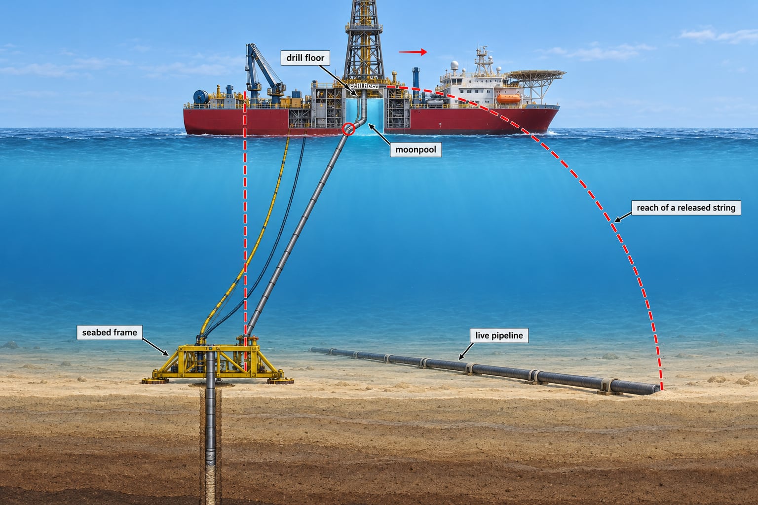
Figure 1. With the string in the ground, the bit and the frame stay put and the string gives first. A string released at the drill floor falls the way it leans, and reaches the line wherever its length exceeds the offset.
What drives the risk
How a DP system is persuaded to drive itself off station
IMO MSC.1/Circ.1580 calls for at least three independent position reference systems for equipment class 2, which “should not all be of the same type, but based on different principles” (vessels built before June 2017, as many geotechnical vessels were, may still follow its predecessor, MSC/Circ.645). The cheapest compliant set, common on survey and construction vessels, is two GNSS receivers and one hydroacoustic system; the illustrative ASOG in IMCA M 220 notes that two of the three references can be GPS. (We quote M 220 Rev 2.1 of 2023; Rev 3 of January 2025 is current.)
Now spoof the area slowly. A single-source spoofer puts the same false signals on every antenna, so both receivers compute the same false antenna position; after the DP applies each antenna’s lever arm they differ by the antenna separation. Close antennas still agree; widely separated ones show a jump and a standing offset equal to the baseline, a signature worth alarming. The acoustic, ranging to seabed transponders, still reports where the vessel is. The estimator, weighted towards the smooth GNSS pair, makes the acoustic look like the reference that is drifting; the divergence test warns against it, and the median test, which M 252 describes as mainly designed to detect slowly drifting references, rejects the odd one out. The odd one out is the honest sensor. M 252 states this for any installation of dual differential GNSS (DGNSS) plus one other reference, particularly when coverage is poor: both DGNSS can drift together, making the third appear to be at fault.
The DP then holds the false position on its setpoint, driving the hull off by the spoofed displacement in the opposite direction, a direction the spoofer chooses; inside the critical zone, some of those lead to the pipe. On screen, GNSS shows the vessel still while the acoustic shows it moving.
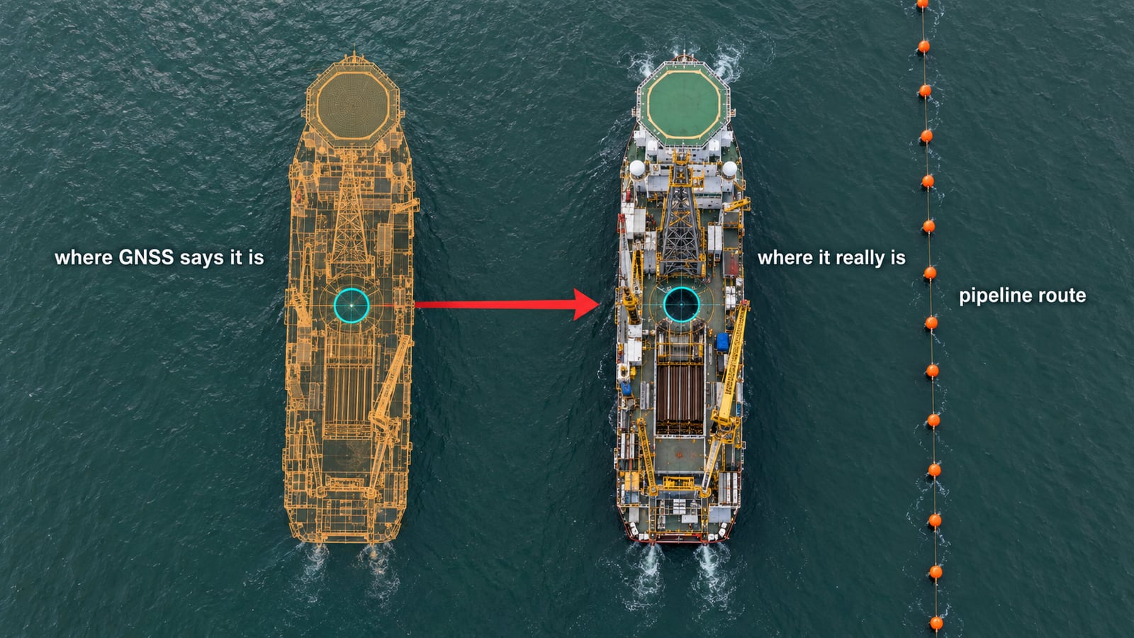
Figure 2. The two spoofed receivers agree, the median rejects the honest acoustic, and the DP drives the hull opposite to the spoofed displacement, in a direction the spoofer chooses.
A slow drag does not need a sophisticated attacker. A blended GNSS-inertial reference gates a large spoofed jump and coasts, but its gate widens, many units re-accept GNSS after a timeout and walk to the false position, and their inertial drift during the coast is a slow drag in itself; IN 1730 warns that blended systems may mask GNSS problems. Without such a walk, a drag of tens of metres needs a spoofer that moves its false position deliberately, which has been demonstrated at sea. Capture is often the most visible moment: a change in signal strength, gain control or receiver clock, or both receivers losing and regaining lock together.
The DP does not stay silent: rejecting the acoustic raises a reference alarm, and with fewer than three references a typical ASOG drops the vessel out of its critical activity mode (CAM). The danger is what the crew concludes. The acoustic is the reference everyone distrusts in shallow water, the GNSS pair agrees, and the natural reading is that the acoustic has failed. A DP operator (DPO) who re-initialises it so it agrees again erases the evidence and plants a false origin the DP will hold once GNSS is finally removed. IN 1730’s indicators of interference help here only if the ASOG says what each one means: sudden or non-random position shifts, stable but incorrect positions, disagreement with other onboard systems, and multiple vessels reporting similar or identical positions.
Why the equipment class gives false comfort
Circular 1580 defines class 2 around a single fault: “a loss of position and/or heading will not occur in the event of a single fault in any active component or system”. Spoofing is one external cause corrupting every GNSS reference at once, the common-mode failure that duplication cannot survive. The circular asks for independent references and for warnings “when the signals from the position reference systems are either incorrect or substantially degraded”; two receivers listening to one sky arguably fail the first test, and a spoofed signal is precisely an incorrect one. It also expects the class for an operation to be agreed between the contractor and its customer on a risk analysis of the consequence of losing position, the right starting point beside a live line.
Diversity in manufacturer, constellation and frequency makes a crude spoofer show as disagreement between receivers. Against a competent one they are two receivers and one source, the single point of failure we traced in where offshore positioning chains break under jamming and spoofing. IN 1730, published in April 2026, says multiple GNSS-based references do not provide true redundancy where the signal is compromised; IMCA M 235 (IMCA S 023), on sharing sensors between survey and positioning, had already called multi-DGNSS full redundancy “not necessarily correct”.
Weighting makes it worse. Variance weighting lets smooth GNSS outweigh a noisy shallow-water acoustic. IN 1730 recommends equal weighting, but weights shape the blended position, not the vote: the median still rejects the lone acoustic. Two GNSS against two other references split evenly, the outcome depends on the vendor, and meanwhile the hull moves at about half the drag rate. Equal weighting is a floor, not a fix.
The honest reference is not always honest
An ultra-short baseline (USBL) fix is a range and two angles rotated into a north-referenced frame by heading, roll and pitch. The DP’s heading sensors are usually gyros, but the heading that rotates the acoustic fix may come from a dual-antenna GNSS compass, and the acoustic solution may be geo-referenced through a GNSS-aided inertial navigation system (INS); a spoofed input to either corrupts it. A long-baseline fix is ranges only and depends on heading only through the lever arm. IN 1730 records that GNSS heading may degrade before position, an early indicator worth watching, and treats sensors shared between survey and DP as both a risk and, in affected regions, a way crews have kept position.
A reference counts here only when the whole chain behind it, heading and aiding included, owes nothing to satellites. We call these non-GNSS references from here on. Their absolute calibration is a separate question, settled against the pipe. Two acoustic systems are one principle, sharing the water column and usually the transponders, sound-velocity profile or heading source, and an INS aided by an acoustic belongs to that acoustic’s principle.
The guideline most specifications still cite
IOGP Report 373-19 / IMCA S 015, the joint document most positioning specifications cite, had its technical content last revised in February 2021. The word spoofing does not appear in it. It treats jamming as a cause of signal loss, mitigated by notices of jamming trials and monitoring, and its statistical testing rests on receiver autonomous integrity monitoring, which checks satellites against each other; a spoofer faking the whole constellation consistently gives it nothing to disagree about.
More telling is its view of redundancy. Written for survey positioning, it recommends two fully independent positioning systems and, after acknowledging that the satellites are often a common element, adds that solutions based on GPS or GLONASS “can be considered fully independent if the associated augmentation systems are fully independent”. That is exactly the logic spoofing defeats, and specifications carry it over into DP. IOGP’s guidelines for drilling hazard site surveys, Report 373-18-1, repeat for the survey vessel the recommendation of two fully independent systems run to 373-19.
Change is coming. IMCA M 252 already warns that certain regions are prone to jamming and spoofing. IMCA’s survey committee recorded in January 2026 that the joint revision of 373-19 / S 015 focuses on jamming, spoofing and multi-constellation systems, and that an IOGP technical flash on jamming and spoofing was about to go to IOGP members; IOGP’s public library held no spoofing guidance when we checked. Meanwhile the gap is in contract boilerplate: “GNSS positioning in accordance with IOGP 373-19” says nothing about spoofing, and counting two GNSS systems as independent says the wrong thing. IOGP Report 624-02-01 (2023), a calibration and verification specification for GNSS, heading and inertial systems written to be included in contracts, is the natural home for spoofing checks.
Jack-ups and fixed platforms
A jack-up moves the risk rather than removing it. Elevated and preloaded it cannot drive off, but most geotechnical jack-ups drill through a moonpool or over the side, not from a skidding cantilever, so the exposure recurs at every borehole, beside the footprints of the last. Most are towed or self-propelled without DP; IMCA M 103 and M 223 cover the DP units. M 103 asks, as a design consideration, that no known single failure cause uncontrolled contact with “an adjacent surface or seabed structure”, which would include a pipeline; a spoofed position is not a single failure in that sense, so the clause does not reach it.
The exposure sits in the final approach and leg lowering, touchdown and preload, and departure, when M 223 prefers extraction in a drift-off, which beside a line must drift away from it. M 223 notes that the legs can mask satellite signals and that, as they are lowered, the problem usually transfers from DGNSS to the acoustic system; it suggests a third reference such as taut wire, laser or radar. Beside a pipeline there is often no structure for laser or radar, and M 252 notes that taut wires seem limited to water deeper than about 20 to 25 m, so the acoustic that would expose a spoofed fix may struggle through the lowering with nothing behind it. Where anchors warp a towed unit onto location: none inside the critical zone, no wire across the line without the operator’s approval and a buoyed clearance, and anchor positions checked against the pipe, not only against the handler’s GNSS.
A spoofed fix at touchdown puts a spudcan where the site-specific assessment did not assume it; for installation, preload and removal that assessment now sits in ISO 19905-4 (2026), while ISO 19905-1 covers the elevated unit. A spudcan need not touch the pipe: penetration displaces soil sideways and can load a buried line. The clearance is usually expressed in spudcan diameters from the spudcan edge and confirmed by the operator’s soil-displacement analysis; ordinary positioning uncertainty comes out of it, but a spoofed fix cannot be budgeted for, only excluded. An old footprint, which M 223 asks to be known for each location, can make a spudcan slide off target; a punch-through can drive it metres deeper in seconds; footprint slopes near the line can slump and leave it unsupported. IOGP 373-18-1 lists, for bottom-founded rigs, pipelines on or below the seabed beside positional tolerance, direction of approach and departure, and spudcan damage.
So no leg touches the seabed on a satellite position alone, however many receivers agree. Immediately before installation, a sector-scanning sonar or remotely operated vehicle (ROV) survey of the location, which IOGP 373-18-1 already suggests near existing installations, confirms the line where it lies. The check that does not share the failure is then an ROV or leg-mounted sonar watching each spudcan against the line, from settling height until every leg is pinned. Where the line is buried and invisible to both, the watch is against seabed markers placed over it on a pipe-tracker fix before the move. A clearance below the assessed value before touchdown stops the leg and the unit repositions; after touchdown, a falling clearance stops the preload and the leg is raised where the assessment permits; and the watch resumes at extraction until the spudcans are clear of the line. An acoustic check before lowering helps but does not cover the lowering.
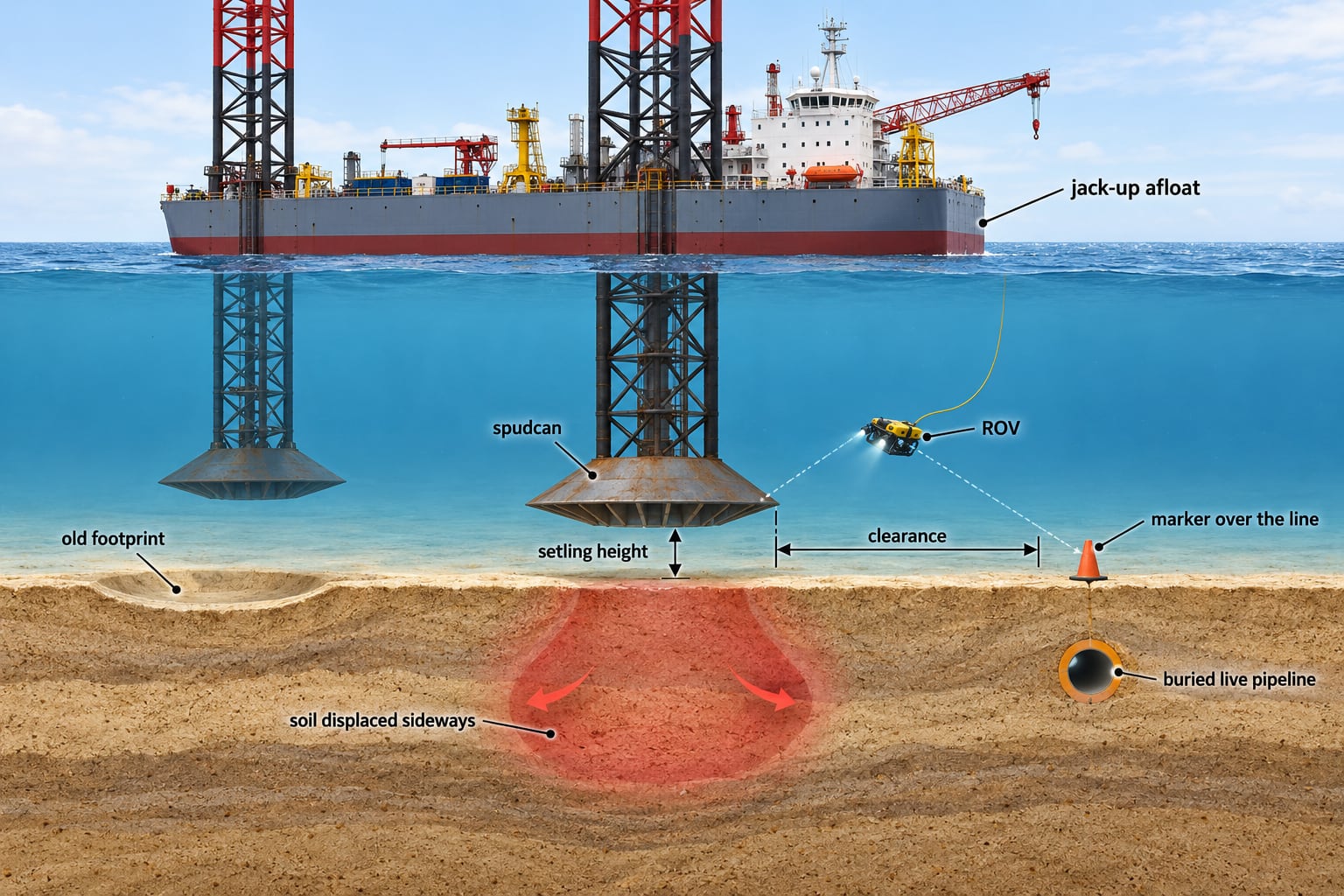
Figure 3. The check that does not share the failure: each spudcan watched against a marker over the line from settling height until the legs are pinned, with the clearance set in spudcan diameters by the soil-displacement analysis.
A fixed platform cannot walk. The residual risk is geometric: whether set-out and the as-built pipe route are known in the platform’s own frame, by measurement from the structure, and whether the entry point is confirmed at the seabed, since a casing through deeper water can deflect in current.
Where the decision goes wrong
1. Treating DP-2 as protection against spoofing
The class answers “will a single failure lose position?” The operator needs “will a slowly false position be recognised before the string reaches the pipe?“
2. Calibrating the acoustic array with the system it is meant to check
Array calibration usually takes GNSS as its absolute reference, and IN 1730 records that disruption can be particularly critical in early project phases, during calibration and beacon deployment. An array calibrated under a spoofed fix is internally consistent and absolutely wrong, and holds the vessel perfectly still at the wrong offset.
3. Letting the project merely acknowledge the ASOG
IMCA M 220 wants the crew to own the ASOG, with sign-off by master, chief engineer, senior watchkeepers and DPOs; in its illustrative example the client’s line reads “seen/acknowledged”, and the suggested signatories are “for guidance only and may be altered”. By default the document is owned by the contractor’s crew and acknowledged by the operator’s project team, both with a standby or schedule reason to set triggers loosely. The example’s one real lever, no resumption after yellow or red without client concurrence, is waived for “proactive” or “precautionary” yellows declared by the vessel’s own team, which is how a suspected spoof will often be declared. Beside a live line the ASOG should remove that waiver for spoofing triggers and give the concurrence to the asset owner, the person accountable for the pipeline inside the operator and outside the project’s management chain.
4. Placing jack-up legs on satellite positions
A misplaced leg is discovered when it is already in the ground.
Where the gap is most likely to open
Contractors and operators with long DP histories beside live assets already design against common-mode reference failure, and in our experience the major international engineering, procurement and construction contractors treat these hazards as established practice; spoofing extends a hazard they know, though even their procedures must now name it.
The exposure is greater with regional operators and contractors building their own offshore competence, and not for lack of capability. It sits where four conditions meet: routine interference; specifications citing the 2021 GNSS guideline as if it settled spoofing; the cheapest compliant reference set; and an ASOG carried over without a spoofing trigger. The same can arise inside a major operator’s project wherever the geotechnical scope is subcontracted to a local spread, the chain IOGP Report 423 on managing health, safety and environment in a contract environment is written for. There, a DP-2 notation and a signed ASOG look like the finished answer when they are the starting point.
How to take the risk to ALARP
ALARP (as low as reasonably practicable) asks that a measure be taken unless its cost is grossly disproportionate to the risk it removes. Beside a live pipeline, more measures survive that test than most permits demand.
Change the tool before changing the rules. Ask the geotechnical designer which of the closest positions truly need a drilled borehole. Beside the pipe, an ROV-deployed cone or push core, placed by sight of the pipe, removes the heavy rig and takes the satellite out of the placement, though the ROV’s mother vessel is still on DP. A seabed CPT rig or drill has no rigid link to the hull and is pulled only once its umbilical slack is used, but it is placed on a USBL fix only as good as its tie to the pipe, and a deep push can take tens of minutes to retract. Every option still lands a heavy object beside the line. Reject each on a written cost; that record is the ALARP case.
Define the critical zone from reach, and grade it by consequence. The zone is the distance within which the worst credible excursion, with the reference configuration actually used at that distance, brings the string, the frame, a toppled string or a dropped object onto the line, over the demonstrated time to detect, decide and act (including GNSS removal and pick-up or disconnect from the deepest penetration), with landing tolerance, catenaries and nearby transponders included. The excursions are a conventional drive-off or drift-off and a slow spoofed drag, the latter taken as the largest hull displacement a drag can reach before the first DP rejection or ASOG yellow trigger fires, plus the drag over the demonstrated time to decide and act, at the fastest rate no rate-based DP test catches. Where GNSS governs, that drag has no bound, so two geo-fences computed from non-GNSS references guard the zone: an inner one, placed so that the drag over the response time after it alarms still leaves everything clear of the line, raising a yellow, and an outer one at the zone’s edge, raising a red. No work is done within reach of the line outside the reference rule below. Consequence is graded from the line’s actual condition, burial from the latest survey, remaining wall, pressure, coating, impact capacity, spans and any buckling since lay, through a recognised method such as DNV-RP-F107. The operator’s pipeline engineer owns the zone, and it goes out with the tender because the reference configuration, the shut-in decision and the price all depend on it.
Set the reference rule once. Inside the critical zone:
- Three or more non-GNSS references, agreeing and verified, with no one principle holding half or more of them (two acoustic systems, or an acoustic and an INS aided by it, are one principle): the target. GNSS may be deselected by plan; in shallow water keep one non-GNSS surface reference (laser or radar) or one GNSS input in, as M 252 recommends, deweighted where the DP allows, and the median still outvotes it.
- Two non-GNSS references of different principles, agreeing and verified (an acoustic array’s absolute tie against the pipe; relative references such as taut wire initialised at a verified position), with one GNSS input on line (one receiver, or the pair blended into a single input), deweighted where the DP allows, so the DP keeps three references and a median: work is permitted, including new frame landings. GNSS still votes in that median and decides it whenever the two non-GNSS references disagree, so any DP rejection of a non-GNSS reference while GNSS is in the solution is a yellow trigger.
- Anything else, including two references of one principle, two with GNSS out, or two GNSS inputs beside two non-GNSS references (a median split): no new frame landing, borehole or clamped test.
“Different principles” is on record for a reason. IMCA’s DP event DPE 04/23, “Position reference problems again! The dangers of recalibrating” (December 2023), is the mirror image of a spoof: a diving vessel in about 25 m of water on two DGNSS and two acoustic references, water-column conditions and reflections corrupting both acoustics, the DPO recalibrating one DGNSS and then every reference, and the vessel carried 40 m off its setpoint in 40 minutes.
Make non-GNSS references govern. Seabed-transponder acoustics, long-baseline where the schedule allows, taut wire where depth suits, and an INS aided by the acoustics or a Doppler velocity log (DVL). Unaided, a navigation-grade INS coasts for the minutes needed to act, not for holding station, and one that was GNSS-aided during the drag starts with the false position and velocity; the grade trade-off is one we work through for subsea vehicles in when tactical-grade IMUs earn their premium. A bottom-tracking DVL measures the creep the spoofed receivers report as zero. Alarm a deselected GNSS against the non-GNSS references through a comparison the vendor confirms, since the DP generally stops testing it. Prove the configuration on DP trials, away from the pipeline with the vendor present, by injecting a common-mode drift into both GNSS feeds and recording what the median, estimator, thrust demand and hull motion actually do, and address GNSS common-mode failure in the FMEA, as IN 1730 asks (IMCA M 166 is the FMEA code of practice).
Harden the receivers anyway. Multi-constellation, multi-frequency receivers, authenticated signals where available, anti-jam antennas and receiver-level spoofing detection, with live monitoring of signal strength and gain, GPS-only against multi-constellation solutions, correction status, GNSS time against a stable onboard clock, and the inter-antenna offset against the surveyed baseline. Corrections are a separate route in, as we set out in what to do about spoofed DGNSS corrections. None of this defeats a competent spoofer; it sits beside the non-GNSS references, not instead of them.
Tie the geometry to the pipe, not to the sky. Before the frame lands, confirm the offset against the pipeline itself: an ROV visual fix, a pipe tracker, or an acoustic survey of the line from the array. Calibrate the array in a local frame tied to fixes on the pipe; for the vessel’s USBL, IOGP Report 624-01 sets out verification and when recalibration is required.
Let the spread be the witness. A transponder on the seabed frame tracked from the hull; string and lift-wire angle; compensator stroke and torque; frame tilt; DVL; moonpool and frame cameras or sonar looking at the line. IN 1730 notes that mission equipment such as subsea acoustic references may add position inputs; the drilling-spread examples are our extension. In 20 to 50 m of water they are as fast as the DP alarm, and none of them can be spoofed provided the USBL and DVL take gyro heading. Three limits matter. The frame beacon is tracked through the hull’s acoustic transducer, so it is good evidence against GNSS but cannot arbitrate between acoustic references, and it is lost when the acoustic is; between non-GNSS references, arbitrate on string angle, DVL or an ROV. Range alone has no direction: from the pipe side, the range to the frame falls as the hull moves away from the line until it passes over the frame, so direction comes from the beacon’s position on gyro heading or from the string angle. And compensator stroke shows that the hull has moved, not which way.
Make the ASOG settle these, and prove them. An article cannot write a vessel’s ASOG, because every step of a sequence changes what the DP believes and where the hull goes, and only the vessel’s own DP can show what that is. The operator should require the vessel’s ASOG to settle the following principles and prove the sequences that implement them on its own DP in the injected-drift trial and the on-board drill.
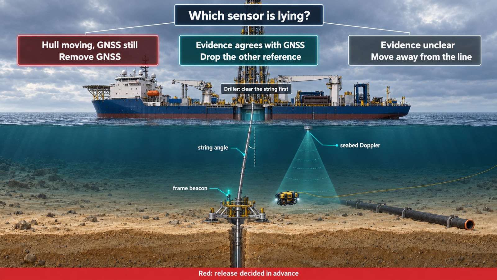
Figure 4. The seven principles in one picture: the spread, not the reference count, decides which sensor is lying.
- Evidence decides, not reference counts. When the spread shows the hull moving in a way GNSS does not show, GNSS is lying: it comes out of the solution, whatever the number of references left, provided a non-GNSS reference the spread supports is in the solution once it is out (point 2 says how). It also comes out when it disagrees with two agreeing non-GNSS references of different principles. Where no such reference can enter, the DP goes to joystick with automatic heading on gyro and, once the string is clear, moves away as in point 4. The DP’s median does not wait: in the common two-GNSS, one-acoustic set it has already sided with GNSS, so leaving everything as it is means following the spoof.
- One removal sequence, proven. GNSS is removed by the single sequence in the DP vendor’s letter, proven in the trial, that resets the estimate to the non-GNSS references and the setpoint to the resulting present position in one operation; the pass criterion is no step in thrust demand or in the ranges to two transponders at well-separated bearings, and those ranges no longer trending once GNSS is out. The letter covers every starting state, including the one the median creates on two GNSS and one acoustic, where the acoustic is already rejected and will fail the DP’s prediction test if simply reselected. Where the DP has no single operation, the steps are ordered so that it is never without a reference in the solution and the hull never moves further along the drag: the non-GNSS reference the spread supports enters by the vendor’s reset-to-reference function, never by re-origin, no later than the last GNSS input leaves, and GNSS leaves before any non-GNSS reference the spread supports is deselected. The DP then returns the hull along the drag as a response to a position error, not as a setpoint move; the trial measures its speed and overshoot, and the pass criterion becomes no movement further along the drag, with return speed and overshoot within the ASOG’s limits. With the string in the ground that return is allowed only if it meets those limits; otherwise GNSS stays in until the string is clear. A DP that can do none of this does not work inside the zone on that configuration. Never enter the non-GNSS coordinates as a new setpoint while GNSS is still in the solution: the DP would drive the hull as far again the way it has already gone.
- No re-origin. While any disagreement or suspected spoof persists, no reference is re-initialised or re-origined. A non-GNSS reference the DP has rejected is re-admitted only on spread evidence and by the same sequence; one the spread shows to be wrong, with GNSS agreeing with the spread, is simply left deselected. A taut wire that sides with GNSS against an acoustic during a drag is suspect first: the drag pulls its weight.
- When the evidence cannot decide, move away. The evidence cannot decide only when the spread evidence is missing or contradicts itself (string clear and frame beacon lost; string angle and beacon disagreeing; or two non-GNSS references disagreeing with the string clear and no DVL or ROV to arbitrate), never because of how many references remain. Then change no reference and enter no absolute setpoint. With the string in the ground, hold the setpoint while the driller clears it; the red limits on string angle and beacon offset still apply. With the string clear, make relative setpoint moves away from the line on gyro heading, heading setpoint fixed, at a speed above the rate the disagreement is growing, each larger than the present disagreement plus its growth over the move, until every reference, taken separately, puts the hull outside the zone. Where nothing can confirm the moves, take the DP to joystick with automatic heading on gyro and move away on thrust, with DVL bottom track where fitted. A relative move carries the hull the commanded distance only while the errors in the solution stay constant: the drag continues after the move, and a reference rejected or re-accepted during the move steps the hull by up to the disagreement.
- The driller clears the string first. At yellow: stop rotation and any push; retract the cone or pull the wireline tool; open the clamp and pick up until the bit is above the frame and the bottom of the string is above the line and its cover; report “string clear”. With the string still in the ground, any return is towards the frame, in increments at a speed above the rate the hull is being dragged (zero once GNSS is out), each confirmed by the string angle or the beacon’s position on gyro heading; beyond a lean limit set in the ASOG the hull returns over the frame before the pick-up, because pulling a leaning string loads the frame. Apart from the return in point 2, never a DP step to a coordinate.
- The release is decided in advance. Whenever the frame is landed inside the zone, the lift-wire winch stands in constant tension below the frame’s sliding resistance, paying out as the hull opens from the frame, with a weak link only at the drum anchorage and a breakaway connector on the umbilical rated below the frame’s sliding resistance. At red: never disconnect at the drill floor while the string leans towards the line, because it falls the way it leans. First move the hull over the frame, by point 5’s increments, or beyond it on the side away from the line; if that is impossible, release at the pre-set release point low on the string, so the length left standing cannot reach the line, and at once pick up the string left hanging from the hull; until it is above the line and its cover, the hull moves only away from the line. By default leave the frame where it stands, and lift it only with the hull over the frame or on its side away from the line. Whether a latched wireline tool is pulled or its wire cut is decided in advance, and every time is demonstrated in the drill. The move-off is a relative move on gyro heading away from the line, at a speed above the rate the hull is being dragged while GNSS remains in the solution, continued until every reference taken separately, and the frame beacon, put the hull outside the zone. It is confirmed by the hull’s position relative to the frame moving away from the line (an offset on the line side shrinking, then an offset on the far side growing), from the frame beacon’s position on gyro heading or, where it is lost, from DVL bottom-track displacement on gyro heading or the frame camera or sonar, not by range; the string angle confirms only while the string still stands in the frame. Where none is available, or the confirmation does not show the hull moving away as commanded, move off in joystick with automatic heading on gyro.
- The triggers map onto the vessel’s own statuses and never lower them. IMCA M 220 uses green, advisory, yellow (“prepare to suspend”) and red; at yellow this goes further. Every yellow and red notifies the asset owner and the field control room.
- Advisory: interference advisories, military vessels nearby, or other vessels affected; a receiver degraded; GNSS heading unstable; GPS-only disagreeing with multi-constellation, or abnormal correction status; GNSS returning after an outage, or both receivers losing lock or dropping precise mode together; GNSS time drifting; signal or gain anomalies; the inter-antenna offset leaving the baseline; a deselected GNSS disagreeing with the non-GNSS references. After any outage GNSS is proven against the non-GNSS references before it re-enters.
- Yellow: GNSS in the solution disagreeing with the non-GNSS references beyond the ASOG limit, set tighter than the DP’s rejection limits over a stated averaging window; a DP rejection of a non-GNSS reference while GNSS is in; non-GNSS references disagreeing with each other; the references falling below the rule; the inner geo-fence alarming, computed from each non-GNSS reference and the frame beacon separately; frame-beacon offset, string or lift-wire angle, or mean compensator stroke past its yellow limit, whatever GNSS says.
- Red: the outer geo-fence alarming, computed the same way; frame-beacon offset, string angle or lift-wire angle past its red limit; the hull moving on spread evidence, other than as commanded, once GNSS is out of the solution, the return in point 2 counting as commanded (the GNSS offset itself keeps growing while the spoof lasts and is not a trigger); no non-GNSS reference left in the DP solution, lost or rejected, while GNSS is out or disagreeing; the deselected GNSS and a rejected non-GNSS reference both disagreeing with the DP position in the same direction.
- One approved exception: removing GNSS in response to a trigger or a suspected spoof counts as the loss of one reference however many receivers it covers, and the status after it is never lower than yellow. GNSS deselected by plan before the frame lands, under the first line of the reference rule, carries the status the vessel’s ASOG gives the references that remain. The independent specialist approves this mapping.
Plan the closest boreholes, weather permitting, so a blackout drift carries the vessel away from the line, and let go no emergency anchor inside the zone. Drill the scenario on board before the first borehole inside the zone, using IMCA’s guide to DP drills (M 273, 2026) and IN 1730’s advice to train DPOs on spoofing through drills. Rehearsal alone will not stop crews under schedule pressure bypassing guidelines, even ones they helped write, as we examined in why crews bypass the ASOG on drift-off; independent approval and the asset owner’s concurrence are the counterweight.
Have the ASOG approved by someone with no stake in the schedule. This is our working group’s position, beyond current IMCA guidance but within M 220’s allowance for altering the signatories. The ASOG and its reference configuration should be approved by an independent DP specialist appointed and paid by the operator, outside the project’s management chain, for demonstrated DP assurance and position-reference competence. IMCA’s DP Practitioner Accreditation Scheme (IMCA M 249) is a useful baseline, but IMCA Information Note IN 1726 (April 2026) is explicit that practitioner recognition “does not indicate expert status or decision-making authority”; the specialist’s authority comes from the appointment and the permit.
The crew still owns and writes the ASOG; what changes is who approves it. M 220 asks that, on drilling units and similar mission vessels, the driller or superintendent be involved, and beside a live line the drilling superintendent should sign. The specialist approves, witnesses the spoofing drill, and can withhold acceptance before mobilisation and before the first borehole inside the zone, but holds no command authority offshore, where the master’s authority is unchanged. M 220 lets the ASOG be modified in the field with the master’s consent under the contractor’s management of change; inside the zone, changes to spoofing triggers, reference configuration or release decision return to the specialist before the next borehole, never limiting the master’s right to stop. Closing the specialist’s findings is a condition of the permit; the cost is a few days of review against vessel day rates and a hydrocarbon release.
Bring the operator’s consequence controls. The vessel controls likelihood; the operator controls consequence. From strongest: shut in and depressurise the section for the closest positions; failing that, shut in between the nearest subsea isolation valves, using an isolation plug only where one is already planned for the tie-in; reduce pressure, which makes contact less likely to become a hydrocarbon release and any release smaller, at a level the pipeline engineer sets against dent tolerance and flow assurance; protect exposed sections. Confirm from test records that the bounding valves close in time, know the depressurisation time, and make lost communications with the field control room a shut-in trigger. A mass-balance leak-detection system will not see a small leak. Write the response to a hit into a bridging document between the vessel’s and the field’s safety management systems, of the kind IMCA M 125 describes and notes could equally apply to “underwater operations carried out on a field operator’s subsea facilities”, and IOGP Report 423-02 provides as a client template the contractor completes; a gas release under a DP hull is a vessel emergency too. Survey the line before the first borehole and after the last, by visual, tracker and multibeam as its burial requires, with a cathodic-protection check, and again after any red-level string release, dropped object or yellow status with a string in the ground. Backfill or grout and record every borehole in the zone or under the future foundation.
Agree the stop conditions before anyone is offshore. Stop means the yellow driller actions, or at red the red actions, and no new work, whenever any yellow or red condition of the ASOG is met, whether or not interference has been reported; and in addition when the array cannot be verified against the pipe or communications with the field control room are lost. Put them in the bridging document beside the field’s authority to stop work. Written in advance, a stop is procedure; improvised offshore, it is a commercial argument on a moving vessel.
The contractor’s side of the table
A specification written only from the operator’s chair will fail in the field, and the contractor’s objections are usually well founded.
Non-GNSS references cost money and have limits. On two GNSS and one acoustic, demoting GNSS leaves one reference, so the rule means more non-GNSS references of more than one principle, which costs equipment and time. Acoustics degrade in shallow water, under thrusters and near structures; M 252 notes that most vessel operators and suppliers regard 20 to 30 m of water as shallow for DP, and IMCA’s recommended practice for shallow-water DP operations, M 263, covers the same ground. Every transponder and clump weight is also an object lowered near a live line, which M 252 asks to be handled with considerable care.
The spread may not have the tools. Many geotechnical drilling vessels carry no work-class ROV. Confirming the offset against a buried pipe, which multibeam cannot see, may need an ROV tracker from a second vessel, with the simultaneous operations planning IMCA M 203 covers. Cheaper routes: a hull-mounted sub-bottom profiler pass positioned in the array’s frame, or, where the array was calibrated in verified-clean conditions, the operator’s latest tracker survey; IMCA S 029 covers depth-of-burial measurement.
Standby is real money. Geotechnical work is usually paid on a schedule of rates, and interference downtime is usually booked to none of them. Stopping on every anomaly where anomalies are daily stops the job, which is why the ladder separates advisory conditions from stops and why a vessel with enough non-GNSS references can work through jamming. Define interference downtime as its own rate category, as weather downtime is, and issue it with the tender so bidders can price it.
Conflicting requirements are common. Specifications that demand three references on two principles, forbid reliance on GNSS near assets and assume acoustic performance the water cannot deliver are regular. A contractor who flags it at tender does the operator a service, and the operator should pay for the configuration, pipe verification and calibration time it requires.
What goes in the scope
In time order, each with its owner and hold point; the content is as set out above, and arranged by topic in the readiness checklist.
- Line condition: operator’s pipeline engineer; before the scope is issued.
- Substitution record: operator’s geotechnical designer; before the scope is issued.
- Critical zone on assumed times, independent DP specialist engaged, interference downtime rate: operator, the zone stating its assumed reference configuration, limits, drive-off rates and response times; with the tender.
- Receivers and monitoring: contractor, antenna baseline surveyed; fitted before the trial and verified against IOGP 624-02-01.
- Reference configuration, DP vendor letter and draft ASOG: contractor; before the trial.
- Injected-drift trial and FMEA addendum: contractor; approved with the configuration by the specialist before mobilisation.
- Final ASOG and spread monitoring: contractor with its drilling superintendent; approved by the specialist before mobilisation.
- Consequence controls and stop conditions: operator with the field; in the bridging document before mobilisation.
- Jack-up placement, where used: contractor; method and ISO 19905-4 assessment accepted by the operator’s pipeline engineer before mobilisation; spudcan watch recorded through installation and extraction.
- Baseline line survey: to the pipeline engineer’s specification; before the first borehole.
- Zone confirmed: array calibrated and tied to the pipe; zone re-accepted on times demonstrated on a borehole outside the zone to the deepest planned penetration (or a trial position where every borehole is inside it), with the signed drill record; ASOG limits revised and re-approved by the specialist; if the zone grows, items 3 and 5 to 9 reopen; all before the first frame landing inside the zone.
- Close-out: contractor; as-left and post-event surveys to the pipeline engineer’s specification, and backfill records; before the permit closes.
None of this is exotic; most of it exists in IMCA and IOGP guidance or experienced DP contractors’ practice. The working group’s additions are independent approval, the reference rule that lets non-GNSS references govern, the evidence-first decision on which sensor is lying, moving away when the evidence cannot decide, leaving the frame by default at red, the status mapping for a GNSS removal, removing the precautionary-yellow waiver for spoofing and giving resumption to the asset owner, and interference downtime as its own rate. What the spoofing threat changes is that these become the minimum for any borehole in critical proximity to a line that is still live. The equipment class tells the operator the vessel will survive a broken thruster. Only the operator can make sure it will also survive a lie.
Standards and guidance referenced: IMO MSC.1/Circ.1580 (2017) and MSC/Circ.645; IMCA M 103, M 125, M 166, M 203, M 220 (Rev 2.1 text; Rev 3, January 2025, current), M 223, M 235 (IMCA S 023), M 249, M 252, M 263, M 273, S 029, Information Notes IN 1726 (April 2026) and IN 1730 (April 2026), and DP event DPE 04/23; IOGP Reports 373-19 / IMCA S 015 (technical content February 2021; revision in progress), 373-18-1, 423, 423-02, 624-01 and 624-02-01; ISO 19905-1 and ISO 19905-4 (2026); DNV-RP-F107. This article reflects the collective operational experience of the working group and does not describe any specific project, operator or vessel.
Published by
Positioning & Geodesy Working Group
GNSS, INS/IMU & Coordinate Systems
A working group of positioning specialists covering GNSS, inertial navigation, datum transformations, and geodetic network design for marine and land survey operations.
Read next
Assured PNT for offshore vessels: when LEO backup pays and when it doesn't
A senior engineering read on DNK's LEO-based A-PNT programme with Iridium – where backup positioning against GNSS jamming and spoofing earns its keep, and where it doesn't.

Synthetic data for MFL inspection: a buyer's guide to model-trained classifiers
Synthetic data can fix scarce defect samples in pipeline MFL inspection – but only if you validate against real digs. How to specify and buy it without importing risk.

Freelance competence validation – what are the choices?
How does someone in the large freelance market for offshore survey demonstrate competence. Are CVs enough still, and are CVs even believable?
Offshore Geomatics Foundation Certificate · October 2026
Turn reading into certified competence
Decisions like this one are easier to defend when the fundamentals behind them are certified, not assumed.
Early-access list gets 40% off at launch. No spam – the waitlist is only ever used for the certificate. What the certificate covers →